Zaph|Audio - ZDT3.5
"ZDT3.5"
Zaph|Audio Dayton Tower 3.5 Way
 June 6, 2008 - Featured in PE flyer
June 29, 2008 - Added more tweeter level options and commentary July 12, 2008 - Added "ZD3C" center channel option
Introduction Multiple way systems, particularly those with high end European drivers, tend to be ridiculously expensive and complicated. The goal for this system is inexpensive and simple, all while maintaining high performance. It's no small feat, and I feel it's only a possibility with this particular driver combination. With lesser drivers, I'd ask "why bother with a 3-way." Building a European "high end" 3-way, I'd ask "where did all my money go?"
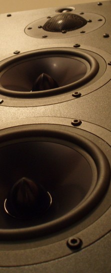
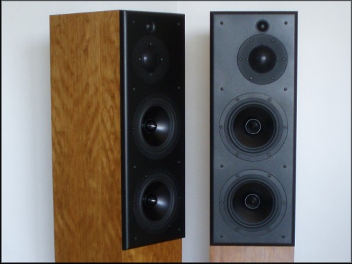
This is a slim tower enclosure with a 9" wide cabinet. It's pretty obvious that the old and large 3-way cabinet styles from the 60's, 70's and 80's are no longer popular, and with good reason - nobody wants big "monkey coffins" in their living rooms, myself included.
|
Crossover
3.5 way crossover at 850 and 3500 Hz
The crossover is 2nd order at 850 and 4th order at 3500. The midrange and tweeter are wired in phase with each other but out of phase with the woofers. The lower woofer uses a large inductor for baffle step compensation and is hooked up with a cascading topology. This means both woofers use the same rolloff components but the lower woofer has an additional component to compensate for the transition from 2pi to 4pi space.
Electrically, the woofers are 2nd order with a multi-purpose zobel. The midrange uses a single capacitor for the high pass to reach LR2 along with a impedance flattening notch to keep the rolloff under control. The midrange low pass uses 2 components plus a small capacitor shunted across the inductor as a notch filter centered at the dome's 13kHz breakup. This not only stamps out the breakup, but helps us hit a 4th order target with minimal components. The tweeter has a more standard configuration with a low Q 3rd order electrical to hit the 4th order rolloff. Both the mid and tweeter use a single padding resistor, simplifying the ability to level match the drivers.
Many components in this crossover serve multiple purposes in the quest for simplification. For some who are used to seeing standard topologies in crossovers, it may not be immediately apparent what every component is for.
Component list
All parts for this system are available at Parts Express. As shown here, I've preselected the crossover parts that will keep the costs down. This includes some electrolytic capacitors for the larger values. The two negatives of electrolytics are lower power handling and degradation over time. Sound quality is not a negative, though many would have you believe that. In my opinion, electrolytics sound every bit as good as poly, mylar or metal film capacitors. There is a lot of hype over more expensive capacitors. You either have to believe me or be willing to spend nearly $600 for a pair of crossovers rather than $160. If you feel strongly about capacitor quality, it's certainly up to the builder.
Some of the electrolytics in this crossover are doubled up for power handling. As far as degradation, if you still have these speakers in 15-20 years, that's when you'll have to begin worrying about it. Being realistic, it's unlikely anybody will own a speaker long enough to worry about the electrolytics degrading. On the other hand, if you plan on this being the last speaker you ever build in your life, (and you're young with lots of life left) you might consider a move to poly caps for the big values.
Be aware that 3 caps are paralleled for C10, to specifically reach .30 uF. Common single cap values such as .22 and .33 will not be a precision strike on the mid dome's breakup node. For resistors, nothing special except that R14 is modified to compensate for the inductor DCR in that circuit, while R20 is doubled up for power handling. The large Erse inductor was selected for it's low DCR to keep the overall system sensitivity as high as possible. They are well built, and I like the way they can be screwed into a board. When mounting screws are used, the screw is far enough out of the flux field to not affect the inductor value.
L1 in the tweeter circuit is a .08 mH. This value is important, and a .05 or .10 is too far off. Since .08 is an odd size, I've specified a Jantzen 20 AWG .10 inductor. It will need 7 turns unwound to reach the .08 value. The turns peel off easily, but you will have to scrape the invisible clear insulation off before soldering into the circuit.
For construction of this crossover, I recommend 3 separate boards. One for the tweeter, one for the mid and one holds the filter for the upper and lower woofers. Keeping them separate will keep to things simple and help avoid wiring errors.
Response curves
![[Image]](ZDT3.5-ND20-inbox.gif)
![[Image]](ZDT3.5-RS52-inbox.gif)
![[Image]](ZDT3.5-RS180-inbox.gif)
Nothing too special or surprising about the response curves of the drivers as measured in the box. The mid and tweet are offset to smooth out the on axis diffraction ripple. The mid and woofers are metal drivers and they do have breakup nodes. The RS52's breakup does need to be addressed in the crossover while the RS180's is high enough that it's off the audible radar with our 850 Hz low pass. The ND20 domes are a rear mount fabric construction with response out past 30kHz and no breakup to be seen.
Modeled on-axis frequency response
![[Image]](ZDT3.5-FR-IMP-individual.gif)
![[Image]](ZDT3.5-transferfunction.gif)
![[Image]](ZDT3.5-polar-3500hz.gif)
![[Image]](ZDT3.5-polar-500hz.gif)
![[Image]](ZDT3.5-measured-farfield-tweeter-mid.gif)
![[Image]](ZDT3.5-measured-nearfield-woofers-port.gif)
The design axis is on the tweeter and the design listening distance is 2.5 meters. Anechoic on-axis response stays within a +/- 1.5 dB window for most of the effective range. Some of the chosen tradeoffs can be seen in the individual driver rolloffs. The crossover is functionally LR2 between the mid and the woofer, and LR4 between the mid and the tweeter. The target slopes are not adhered to for much more than an octave and a half past Fc. The woofer and mid both roll off faster further away from Fc. This is a tradeoff resulting from not using a high number of components to hammer the drivers into strict behavior - only enough to get the job done without audible issues. The woofer and midrange breakup nodes are sufficiently controlled at around 35 or 40 dB below reference level.
Transfer functions are smooth and controlled, with the only notch showing up on the midrange dome. While the transfer function on the woofers is not a true indicator of the amount of baffle step compensation in a design, you can see the lower woofer obviously working in a full .5 way configuration. On the tweeter, phase tracking is only ok with the vertical lobing favoring above the axis. There will be no dip at the 3500 Hz Fc when a sitting listener stands up. More components for a steeper rolloff on the midrange would have lowered the primary lobe, but after some listening I deemed it not necessary. In the woofer's range, the 500 Hz vertical polar response shows some droop as the mic moves further above the tweeter axis. This is simply the negative side effect of a .5 way woofer mounted below the woofer run full up to 850 Hz.
Measured impedance close-up
This is a solid 4 ohm nominal design, so be careful with wimpy low end receivers. Impedance drops to 3.2 ohms in the midbass, which is typical for a 4 ohm nominal design. I did seem to power it fine with an inexpensive Panasonic digital HT receiver, and of course my 120w/chan NAD powered it as loud as I could stand.
![[Image]](ZDT3.5-micdistance.gif)
This is a tall array of drivers. Unlike smaller 2-ways, this system needs a bit more distance to properly sum. The image above shows what happens when you get too close - the midbass and upper midrange starts to droop a bit. This is because of the relative distances between the drivers. When you're 1 meter away from the tweeter, you're off the axis from the lower woofer at a 30 degree angle, and it's a few inches further away which affects the phase relationships. It's not too bad but it does affect the tonal balance. That issue, along with the full baffle step compensation means this system needs a medium to large room to fit the 2.5 meter listening distance. I'd 2 say meters minimum, but more distance is better.
Power Handling
RS52 excursion vs SPL, 850 Hz LR2 high pass, 1,2,4,8,16,32,64,128 watts
![[Image]](ZDT3.5-powerhandling-RS52-LR2acoustic-850hz-1-128.gif)
![[Image]](ZDT3.5-powerhandling-RS180-1-128.gif)
Power handling in this system needed a little more thought. Running a 2" dome midrange 2nd order on the low end is always going to be pushing things. For a rough guideline, using Soundeasy I simulated an excursion vs SPL chart for the RS52 as it is used. This is much more than the typical maximum output calculation based on the Xmax and effective diameter. Here we have a fully simulated response using measured T/S parameters (including Vas) along with a baffle diffraction simulation and the actual high pass filter in place. There's a lot of functionality in the Soundeasy enclosure tools that will never be found in other simple box modeling programs. Using all this, we know that RS52 design Xmax will be exceeded with roughly 100 watts at 400 Hz.
A 2" dome is the smallest driver I would ever do this simulation for. Real T/S numbers were possible with the RS52 because the rear chamber is removable (with some cutting) and the center opening through the neo ring magnet is large and free flowing. This allows a good Qts and delta compliance Vas measurement. For tweeters, pole piece restriction prevents an accurate Vas and putting the chamber back on will not get a realistic delta compliance Vas number. Additionally, overload characteristics of a tweeter are not accurately reflected in a published Xmax number.
Even with this 2" dome, this sim is only a rough guideline and my ears had to be the final judge of output potential. At high music levels, I can hear where the dome overloads with some solo male vocals. That's at an uncomfortably high level however. When music with a full spectral content comes along, it's obvious that the woofer excursion is going to be the primary limiting factor. Bass guitar, kick drum, pipe organs (or 1812 cannons for that matter) will overload the woofers just above tuning or anywhere below tuning, long before the mid dome runs out of steam.
Enclosure
![[Image]](ZDT3.5-insides.jpg)
This is a 3 chamber design, the same enclosure I've used for several projects. Removable baffles are a beautiful thing. The lower chamber is empty and is perfect for filling with sand or placing the crossover. The height of the lower chamber can vary to match a required tweeter listening height. The divider between the upper and lower woofer is not required for clean system operation, but it does add rigidity to the enclosure.
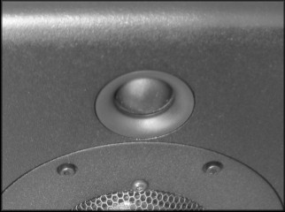
The ND20FB tweeter requires a precise hole to fit. I used a 1-7/16" forstner bit from Grizzly products. Note that you need a drill press to properly use a bit like this. If it doesn't go in exactly straight, the sides will heat up from friction. Since the rear mount requires a 12mm depth and the baffle was 3/4", I went around the backside with a 3/8" ball bearing rabbet increasing the depth until I was at 12mm.
Tower Options
![[Image]](ZDT3.5-options-R4.gif)
![[Image]](ZDT3.5-options-R6.gif)
![[Image]](ZDT3.5-options-L22.gif)
These are common level tweaking options. These will affect the response curves as shown, and also make minor changes in the impedance curves. When purchasing your components, at a minimum I recommend getting a few extra resistors to match levels as required for batch consistency or personal preference. I also recommend wiring the crossover externally until you're sure it's working to your satisfaction. If you're not sure, or if you seem to be having problems but can't figure out where, you may need to invest in a Woofer Tester 3 from Parts Express. This is a great impedance checking tool for those who like to build other people's designs, but aren't necessarily into measurements or crossover design.
Pay particular attention to the tweeter level. Subsequent tests of the drivers used in this system reveal the tweeter to have the most level variance in the group, with a level that could be up to 1.5 dB higher than the design system. As such, R4 may need a 2.0 ohm or higher resistor just to reach the default level. Let your ears be the judge. The mid and tweeter crossovers have been intentionally made easy to level adjust with a single resistor. Don't be afraid at all to try different values.
"ZD3C" Center Channel Option
![[Image]](ZD3C-center-crossover.gif)
![[Image]](ZD3C-center-FR.gif)
![[Image]](ZD3C-center-FR-individual.gif)
The crossover topology is very similar to the floorstanding tower, but with a few changes (in red) and a few deletions (blanked out). It is now a 3-way design, with a mild rise from the lower midrange on up. A good center channel needs wide horizontal response and less baffle step compensation than a floor standing design. The design axis is about 12" above the tweeter and a 2 to 2.5 meter distance. As such, if the center is mounted below the screen, the tweeter should be above the midrange. Mounted above the screen, the tweeter should be below the mid.
The sealed enclosure fits into PE pre-fab 1.0 cu ft MTM enclosure, while the vented needs to be custom built.
It's worth noting here that some builders may be wondering if it's a good idea to just build 3 of this design and use them turned upright for lefts and rights also. In a word, no. There's too much in the design that is specific to center channel usage but not suitable for mains. Controlled vertical off axis with wide horizontal off axis, along with low BSC are perfect for a center, but turn into serious shortcomings when used for an upright left and right.
![[Image]](ZD3C-center-polar-800-3500-sealed.gif)
![[Image]](ZD3C-center-polar-800-3500-vented.gif)
![[Image]](ZD3C-center-polar-1200-poorMTM.gif)
Here we have the worst case horizontal and vertical lobing for the sealed system, and the vented system which has the woofers .75" further away from the midrange to allow for some structural behind the front baffle. Horizontally, the lobing at 800 Hz (purple) is related to the distance between the woofers in the range where the mid is starting to roll off. In general, we get about +/- 25 degrees before the lobing becomes audible, and even then it's not bad at all. This is very good for a center channel and is entirely the reason why a 3-way W-T/M-W format works so much better than a sideways MTM.
For comparison, I've posted the worst case horizontal lobing of a typical 7" MTM laid on it's side. This one is a "BAMTM" laid on it's side. If the system doesn't have a low tweeter crossover point, things get worse at other frequencies with multiple lobing issues all the way up to the crossover frequency. This is the primary problem with most commerical sideways MTM speakers. Anyone not directly lined up with the middle will have 1 or more nulls in the response curve, directly resulting in dialog clarity issues.
![[Image]](ZD3C-center-polar-L16-DCR.gif)
The default value for L16 is a Jantzen 15 gauge air core with a DCR of .38 ohms. This will work well for most people. Since the paralleled woofer DCR is fairly low trough the midbass, the system is sensitive to changes in the series inductor DCR. This directly affects the midbass level and it's a great tweaking option that will help cover the multitude of potential center channel mounting positions. Mid and tweeter level adjustment is done in the same way as the tower options described above.
Tower Room Placement
As mentioned above, this speaker is meant for medium to large rooms by design. As such, you should have no problem placing it well away from the back and side walls for the best sound. Other than that, There are no special placement requirements other than the normal setup advice I usually give. Keep the distances from the back wall, side wall and floor uneven multiples for the smoothest midbass response. "Thirds" would work well - Note the longest boundary dimension and the other two boundary dimensions could be 2/3 and 1/3 of that. This is not a guaranteed method of smoothing room response, but it's got a pretty good chance of working.
If using these speakers in a home theater setup, allow at least a foot between the speaker and the TV.
Summary
3-way and 3.5-way systems are by nature expensive and complicated. Considering that an MTM design with 7" woofers has the same bass radiating surface and output potential, you may to wonder if there really are any good reasons to build a 3.5-way with those woofers. You get 2 primary benefits: a lower distortion midrange and a smoother upper midrange power response. I think people would be very surprised at how these two issues can present a very different, smooth and effortless type of sound, particularly when compared to an MTM configuration. Of course, if you're on a very tight budget, a simpler MTM, or a TM for that matter, may the better option for you.
With this system I've done my best to keep the cost down and the performance high. The wide operating bandwidth of the RS52 dome allowed me to select a low cost tweeter, and keep the woofers operating closer to their optimal range. Multi driver systems like this aren't for everyone, but if you've got the funds, space and the patience to build and finish the large enclosures, you'll surely be happy with the results.
Enjoy!
Page done by John "Zaph" Krutke © 2008
Also visit -Zaph|Audio-