Zaph|Audio - ZA-SR71
Zaph|Audio Seas Reed 7" / 1""ZA-SR71"
December 1, 2007 - Fixed typos, added commentary and options
March 08, 2008 - Added kit soldering tips
Introduction
This year Seas came out with a new series of drivers using reed pulp cones. They fit into the Seas standard product line (now called Prestige) somewhere between the rigid aluminum cones and the highly damped paper or poly cones. The 18cm model used in this design is the ER18RNX. With the 18cm reed cone woofer however, there is one difference: there is a copper sleeve on the pole piece below the gap. This results in a bit lower distortion. It's a step closer to full Excel performance at the lower price point of the standard line. As such, I'm happy to create this new design. I've paired it with a fabric dome 27TDFC, making this a fully alternative version of my popular Seas all aluminum design with the L18 and 27TBFCG.
The new ER18NRX has all of the excellent design elements seen in the rest of the line. A well ventilated voice coil, a behaved cone geometry along with a well designed motor and suspension that has near perfect Klippel test results for BL, Le(x) and suspension stiffness. Seas drivers are certainly not the cheapest, but with their performance in mind they are still one of the best values. These drivers test out very well in response smoothness and harmonic distortion as seen in the driver comparisons elsewhere on this web site.
This kit is available for purchase at Madisound either with or without enclosures, with a 10% discount on the parts.
Crossover
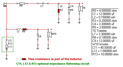
LR4 crossover at 1750 Hz
This crossover is asymmetrical 4th order Linkwitz-Riley at 1750 Hz. The slightly steeper tweeter slope along with a slightly shallow woofer slope helps to align the listening axis with the tweeter.
Electrically, on the woofer we have a simple two component 2nd order network. Also shown is an optional impedance flattening circuit for those with tube amplifiers. (more info on that and other options below) On the tweeter, we have a 2nd order network, a single resistor for level adjustment and a top octave response shaping network. These components combine with the natural rolloffs to hit the asymmetrical 4th order slopes.
A lot of work was put into simplifying the crossover without compromising the system audibly. Some of the details that were sweated over: Did I need to flatten out the woofer breakup, even though it was only a 2dB bump, 18 dB down? Did I need to resolve the on axis diffraction bump at 4 kHz in the tweeter's response? Did I need to resolve the 27TDFC's top octave rise, that seemed to get a little worse after the rest of the crossover was in place? You can look at the schematic and see that the answers are No, No and Yes. I could only give these answers after quite a bit of listening.
I used a Madisound Sledgehammer 15 AWG steel laminate for the primary woofer inductor. Note that using steel screws to fasten the inductor down through the 2 holes will increase the inductance by about .2 mh which is a bit too much for this design. If you would like to mount with screws, buy a 3.0 mH instead. Otherwise, use a non-conductive mounting method like zip ties. Those buying the pre-made crossovers from Madisound should not worry, the inductors are not screwed in. Those selecting their own components could use an Erse inductor, since the screw does not come near the core. Nice inductor design, but a bit expensive. If you are rounding up your own components, be aware that the low DCR of the steel laminate core isn't an absolute requirement. Just try to keep the impedance under aboout .7 ohms and the difference in the effect on the woofer will be minimal.
The Madisound Kit uses a Clarity SA cap for the primary on the tweeter and Bennic Poly for everything else. The SA cap is not the cheapest, but not nearly as ridiculously expensive as a Mundorf or Hovland. I maintain my perspective that high cost components do not perform much better (if at all) than lower cost components. I typically use Bennic Poly caps for everything. If you are building your own crossovers, the Bennics will do fine and be a bit cheaper.
Modeled response
Modeled on-axis frequency response
![[Image]](SR71-modeled-individual.gif)
![[Image]](SR71-modeled-revnull.gif)
![[Image]](SR71-modeled-transferfunction.gif)
![[Image]](SR71-modeled-polar-1500blue-2500red-100step.gif)
![[Image]](SR71-modeled-polar-1750.gif)
![[Image]](SR71-BDS-diffraction-center-offset.gif)
The individual driver rolloffs show that some of the woofer's breakup does remain with the filter in place, but it is not enough to warrant throwing additional components at the crossover. The reverse null is deep enough, showing the crossover point squarely at 1750 Hz. The transfer functions show exactly how the crossover is shaping the response. The transfer function curves are smooth, making the components a little more flexible in spec deviation and adjustment ability. The vertical polar response plots through the spectrum and at the crossover frequency show the vertical listening window to be aligned with the tweeter and fairly tall. While the design listening axis is clearly ears level with the tweeter, there is some flexibility in this regard.
Centering the tweeter is a big design choice for this system. Many people prefer to offset the tweeter while some prefer it centered. The fact is, one is not better than the other, but it does make a difference in how you optimize the system. By nature, an offset tweeter on the baffle will have the smoothest response on axis while a centered tweeter will be a little rougher on axis but smoother off axis. You'll see why in the measured off axis plots below.
This system was designed specifically for Madisound's MD14 enclosure with the pre-cut baffle. Having offset mirror image baffles would have driven the price up for the pre-cut baffles since two different CNC setups would have been required. Then there's the whole issue of keeping the same number of lefts and rights in stock. You can see why it was wise for Madisound to have centered tweeters. No problem here, we'll design specifically for a centered baffle. Three cheers for the router impaired - this is the only design I've ever posted that can be assembled without a router, thanks to the work Madisound has done.
Measured response
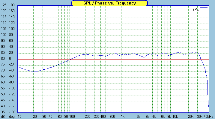
Measured frequency response on-axis, 10ms window
![[Image]](SR71-measured-FR-offaxis-horizontal-15deg.gif)
![[Image]](SR71-measured-FR-offaxis-horizontal-30deg.gif)
![[Image]](SR71-measured-FR-offaxis-horizontal-45deg.gif)
![[Image]](SR71-measured-FR-offaxis-horizontal-combined.gif)
![[Image]](SR71-measured-raw-inbox.gif)
Measured response looks just like modeled, which always brings a sigh of relief from the designer. The dip at 2800 Hz and peak at 4 kHz are tweeter diffraction related. Moving on to the 15 degrees off axis plot, those anomalies are completely gone. In fact, horizontal off axis remains pretty smooth through 45 degrees, where a minor null just below the crossover point begins to show up due to the 7" woofer beaming a little bit at those frequencies.
The primary woofer inductor seems like a large value. In the raw in-box response anechoic plots, it's easy to see why. There is nearly a 10 dB difference between 80 Hz and 1600 Hz. The ER18RNX has a naturally rising response on the top end which the large values in the two woofer crossover components help tame. The woofer's natural response shape combines well with the diffraction ripple to give us a very smooth and controllable in-box response.
![[Image]](SR71-ER18RNX-HD-2.gif)
![[Image]](SR71-measured-HD.gif)
Selecting the crossover point is a fine balance of many issues. One of those issues is using the drivers within their lowest distortion working range. Like many rigid cone drivers, the cone breakup propagates as peaks in 3rd and 5th order harmonic distortion lower in frequency. We want to avoid or minimize those as much as possible. Through the design iterations, the crossover frequency started high and moved down until we get to a point where the woofer's upper end distortion doesn't make itself known. We have to factor in everything here, including tweeter low end power handling, natural response rolloffs, power response and crossover complexity among other things. It's no easy decision. In my opinion, 1750 Hz was the best for this system. A 27TDFC could easily work down to 1500 hz, but only at a certain output level. I favored 1750 over a lower crossover point that would place the power handling limit on the tweeter. Seas woofers handle power well and get very loud, so it's important to make sure the tweeter can keep up.
The system HD curve has baffle step compensation reflected in it, while the infinite baffle HD curve does not. The system curve, which includes the filtered 27TDFC, is semi-near field but closer to the woofer axis to minimize inaccuracy at the top of it's range due to beaming.
The ER18 is extremely clean in the bass and midbass. This, combined with the merely average harmonic distortion on the top end of it's range is part of the reason the design works well with full baffle step compensation. Simply put, a distorted frequency range seems louder than a clean one and it can be compensated for in a response curve. This is essentially adding linear distortion (which is a variation from flat) to compensate for deficiencies in non-linear distortion - a top end that seems a little bit brighter than normal due to harmonic distortion. I didn't need HD plots to see this. The baffle step compensation was selected by ear, and these plots are just information to reinforce what I was hearing.
Be careful about generalizations of what a good number is for BSC. Some less than informed/experienced folks may immediately declare that full BSC is too much. It's all about tonal balance, and there are a lot of issues that affect it. The amount of BSC has to be selected by ear, in room. It's not something that a crossover optimizer can decide for you, and it's not something that can really be decided until the system is heard in a room.
Power Handling
Excursion vs SPL, full range, vented, 1,2,4,8,16,32,64,128 watts
I don't need to go into too much detail in this section. All I really need to say is that this system will surely get loud enough for you, and you probably aren't going to run into any limitations of any kind above 40 Hz, even when run full range.
I could comment on the meaning of power handling beyond Xmax. One thing Seas drivers do very well is thermal power handling and dynamics, something that's a bit harder to quantify with traditional driver tests. You either have to do quite a few additional types of tests (multi-level and Klippel) or at least look into the driver's design features. Seas drivers have well ventilated voice coils, and as a result the coil resistance does not change quite as much under heavy use. The motors in the 18 cm Prestige series are optimized pretty far beyond most of what can be seen coming out of Asia these days, and a lot of that pays off at higher output levels.
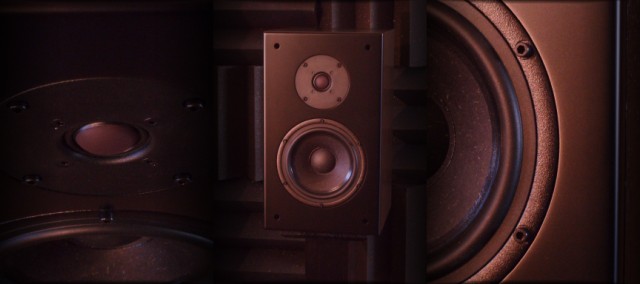
Enclosure
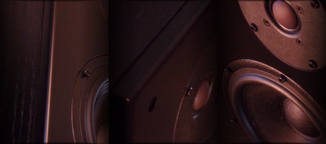
The "SR71" in a radar evading black finish
![[Image]](SR71-back.jpg)
![[Image]](SR71-baffleback.jpg)
![[Image]](SR71-insides.jpg)
![[Image]](SR71-measured-tweeter-shim.gif)
This system is designed specifically to fit in Madisound's MD14 enclosure with their baffle pre-cut for Seas 7" woofers and standard series 1" tweeters. Dimensions are provided for those who would like to build their own however. The fit and finish of the Madisound enclosures is first rate. The "TD" terminal cup and Precision 2" flared port fit perfectly. I did however place a couple of hardwood dowels across the sides to reduce vibration. Any piece of wood or two will do this job fine.
I love "TD" cup terminals. It's not because I support bi-wiring - that's a complete waste of two amplifier channels. Basically, when you're initially hooking up your drivers and testing your crossover, you can wire each driver right to a terminal and have the crossovers external for easy tweaking. Then when things are finalized, you can put the tweeter and woofer filters on separate boards and wire each one to a terminal. Later on, if you ever have a problem such as a blown component or loose solder connection, you can listen to each individually to help isolate it. You can even reverse the phase externally at the terminals to see if you hooked up a driver wrong.
The tweeter countersink is multi-purpose. It's designed to fit a few of Seas newer tweeters with 6mm flanges. For those using 104mm tweeters with 3.5mm thick flanges like the one in this design, a shim or spacer of some sort will be required to bring the front of the flange up to level with the baffle. If you don't do this, there will be some diffraction issues with the exposed ridge. There are a lot of ways to deal with this, such as weatherstripping tape or some rolled sealing caulk. I used 4mm hobby foam from a craft store, cut to a circle with a little hand made wood and razor blade jig.
It would be important to note that I did not round over or chamfer the inside of the woofer hole. I do chamfer the inside on designs with smaller woofers that need a reduction in airflow resistance, but the Seas 7" woofers are well ventilated. All response plots for the woofer as shown in this design are with the precut baffle as supplied. This is partially a concession to those who would like to build the kit but do not own a router. Just be aware that I would not have not have let it go if the effects were obvious and audible. For those who buy the precut baffle and do have a router with a chamfer bit, go ahead and chamfer the inside radius. It's certainly not going to hurt the design, and will likely result in a tiny bit smoother response on the top end of the woofer's working range due to a small reduction in the inside edge reflection back through the cone.
I used Whispermat 3 layer WM2 on the back and bottom and 2 layer WM1 on other surfaces. There are a lot of options for damping, take your pick. Just be careful of carpet padding and generic egg crate foam, as they may not have optimal acoustic properties. If your damping/absorption material is thin, double up on the back and bottom. Note that you can't go very thick up on the top because the inside port flare needs some clearance.
The 2" flared port comes in three pieces - the two end flares and a lengthening middle section. To reach my goal 44 Hz tuning, the middle section needs to be cut to 2-1/4" long. If you'd like to try a higher tuning, eliminating the middle section will result in a 50 Hz tuning. I don't recommend going any lower than 44 Hz because the port length would begin to have restricted airflow against the tweeter and front baffle.
Options
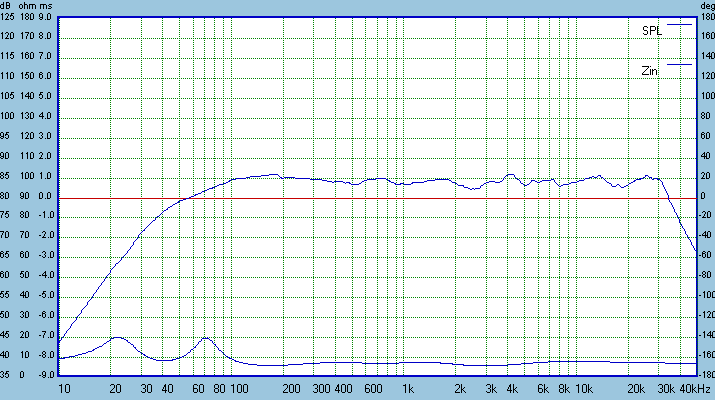
![[Image]](SR71-options-flatimpedance.gif)
Most of the impedance curves shown in this design reflect an impedance flattening circuit. It's not required however and can be removed without any effect if you are using a solid state amplifier. Since this is a relatively sensitive speaker, usage of the impedance flattening circuit could be useful to those who are using tube amplifiers.
![[Image]](SR71-options-tweeterlevel.gif)
This option is primarily designed to help compensate for differences in tweeter levels that occur across production batches. Additionally, it could be used to help you reach your prefered tonal balance. The crossover point or lobing characteristics won't change too much if you keep the tweeter padding resistor within 2 ohms of default.
![[Image]](SR71-options-topoctave.gif)
For most people, the default top octave shelving components will help compensate for the 27TDFC's mild top octave rise. For those who want a little more top octave sizzle or for those listening further off axis than normal, this circuit could be modified or removed.
![[Image]](SR71-options-reducedBSC.gif)
An option for reduced BSC is provided for those who might find a "warm" or "heavy" tonal balance with the default crossover. I recommend starting with the default design, even in smallish rooms, then unwinding the woofer series inductor as needed, along with adjusting the tweeter resistor to match. This option will likely not be needed unless you have very poor positioning like on a bookshelf or near a corner. If you have the Madisound 15 AWG steel laminate, removing exactly 28 turns will turn the 3.3 mH into a 2.5 mH.
If you are going to unwind the standard 3.3 mH inductor, be sure to keep tension on the inductor so it doesn't unravel. This reduced BSC version has been proven to work well in nearfield (about 1m) studio situations with typical console mounting.
![[Image]](SR71-options-L7dcr.gif)
The default woofer inductor DCR is so low that you will only be able to reach it with a heavy gauge steel laminate. If you want to try a different higher DCR inductor, it's not the end of the world, just be aware of the minor change in midbass response that could happen.
![[Image]](SR71-options-offsettweeter.gif)
If building your own cabinets and you choose to offset the tweeter by one inch, this is the on axis response you'll get. (I built this version also to measure and test it) Looks good. The negative will be mildly rougher and non-symmetrical off axis response and vertical off axis lobing that is slightly tilted down on one side and up on the other. The vertical window is still very tall however. If using this front panel layout, the speakers should be toed in to face you.
These options are provided for those who feel the need to tweak. Be aware that for most people, no changes will be required at all, but don't be afraid to try them. In most cases, it's just a few extra parts to order.
Kit considerations
![[Image]](SR71-options-shuntresistors.gif)
If purchasing the pre-assembled crossover, you can still adjust the tweeter level by adding shunt resistors either across the tweeter terminals or across the tweeter padding resistor. Within limits, this works just as well as removing and replacing the padding resistor
The kit comes with a wad of Acousti-stuf. Mount the crossover on the bottom, and cover it well with some of the stuffing. Additionally, take some of the stuffing and tuck it in between the port and the top of the cabinet. Don't allow any stuffing past the internal port flare.
Double up the provided damping on the rear of the enclosure. A single layer is fine on the sides and top. None is needed under the crossover mounted on the bottom. If you are mounting the crossovers externally, then of course you should place damping on the bottom.
The flared port press fits into place in the pre-cut countersunk hole. There are 4 wedge shaped ribs on the insert. I recommend using some sandpaper to rough up the insert flange and pressing some epoxy into the gap from the inside. The port has a tendency to come a little loose otherwise. The two sleeves that connect the middle extension piece to the flanges are tight enough that you don't have to glue them.
The crossover boards provided by Madisound require wires to be soldered directly to the board. Madisound will provide a hookup schematic showing where to connect the wires. There is a trick to soldering wires directly to a circuit board however. It's a three step process - First, melt a glob of solder onto the board. It should not be a bead shape, but a firmly attached mound. Next, tin the wire lead. Finally position the tinned wire over the solder on the board and touch a solder pen to both. When the solder on both surfaces melts together, remove the pen and hold wire in position until it hardens. This will provide a solid connection.
Room Placement
The best sound will be had from stand mounting, about 2 feet out from the back wall, and a minimum of 2-3 feet out from the side wall. As I'll mention for most of my stand mounted projects, keep the distances from the back wall, side wall and floor uneven multiples for the smoothest midbass response. "Thirds" would work well - Note the longest boundary dimension and the other two boundary dimensions could be 2/3 and 1/3 of that. This is not a guaranteed method of smoothing room response, but it's got a pretty good chance of working.
Do not place these speakers right up against a wall, or on a bookshelf. They may be small speakers, but they are not "bookshelf" speakers. They are by design stand mounted main speakers. If you do, you might need to try the reduced BSC crossover. While the frequency ranges affected by baffle step and boundary reinforcement are different, they do overlap and as such one can help compensate for the other. Please be aware that wall or bookshelf mounting is a severe compromise and generally all rectangular box speakers will exhibit ragged midrange response in that case.
As discussed above, these speakers are optimized for off axis listening, and they should not be toed in towards the listening spot. Facing straight ahead will sound the best. If the room requires the speakers to be closer to the side wall than the back wall, then you could toe them inwards to face a point a few feet in front of you. This will maintain the smooth response at the listening spot while limiting early wall reflections higher in frequency that could smear the imaging.
![[Image]](SR71-roomresponse-2m.gif)
This is always a dose of reality and everyone's room response is going to be a little different. The speakers are not toed in; they face straight ahead. The room is 16 ft x 18ft. The speakers are on the 16 foot wall, mounted on 24" stands and the front of the baffles are 28" out from the rear wall and 4 feet from the side wall. The mic is level with the tweeters. There is an absorbtion panel on the rear wall behind the speaker. Things are ragged but relatively flat and acceptable to my ears. The primary node at 75 Hz is always there in my room no matter what I do, but using my sub crossover I can minimize it by setting the high pass to 100 Hz but the low pass to 50 Hz. Or, I can leave the sub crossover Fc alone and just dial in a high Q notch at 75 Hz with the parametric EQ. With any speaker, it takes a bit of experimentation to get the in-room sound the smoothest it can be and I encourage everyone to put a little work into it.
Summary
Here we have a smooth, clean system that is relatively easy to construct. With the prefab cabinets, a finished system is only few hours worth of assembly. (or a few days, if you obsess over the details like I do) A speaker with this level of performance could likely go for upwards of a couple thousand dollars in the retail market. Consider a DIY speaker system if you want a high end speaker without paying for a company's marketing and overhead expenses. If you're handy with woodworking, you can save even more.
The ER18RNX is an excellent new product from Seas, and the 27TDFC tweeter makes a perfect mate. This combo, while not as cheap as something Asian made, isn't as outrageously priced as some high end drivers and still right near the top on the value/performance chart.
Enjoy!
Page done by John "Zaph" Krutke © 2007
Also visit -Zaph|Audio-