Zaph|Audio - ZMV5 - MCM / Vifa 5
Zaph|Audio MCM / Vifa 5" System"ZMV5"
Introduction
This system is a bargain priced 5" two way designed for 2 channel setups as well as home theater. When used as a 2 channel standalone system, the design has excellent bandwidth and smoothness though limited output. For home theater usage, the system is effectively designed to be a point source, meaning off axis response is nearly identical in both the horizontal and vertical directions. More specifically, that means this speaker can be laid horizontally for use as a center channel without the dialog disappearing for those sitting off to the side. A subwoofer with a proper active crossover is recommend for home theater usage, or medium to high level 2 channel usage.
The MCM 55-3870 woofer ($18) and the Vifa DQ25SC16-04 tweeter ($16) were perfect candidates as both are value/performance leaders. The Vifa's clean bottom end and small flange allow us to cross over low and keep driver center distances close, meeting our off-axis goals. The build quality of this woofer is phenomenal for it's price, with a well ventilated cast frame. Test results of both drivers are shown elsewhere on this web site in their respective test groups.
Options are available for an alternative tonal balance that different builders may favor or require for less than optimal installations. The bottom line is that it's a cheap, flexible and great sounding design. There are some limitations, but considering the price they are minor.
Crossover
LR4 crossover at 1950 Hz
The crossover is an acoustic 4th order at 1950 Hz, and is nearly a symmetrical Linkwitz-Riley thanks to the woofer's shallow acoustic center. To reach the target slopes, 2nd order electrical plus an L-pad was used on the tweeter, and 3rd order electrical was used on the woofer. The tweeter has an impedance peak to deal with, but I was able to get enough damping out of the shunt resistor to not need an impedance flattening LRC circuit. The woofer has a breakup node but it was high enough to not require extra components in the crossover.
Here's the component list for the default crossover from Madisound:
If you require the alternative crossover shown in the options below, you will be able to unwind L6 and L9 to reach their new values and a swap out of R4 will do the job. As a reminder, do not use steel screws to fasten down the steel laminate inductor as they will change the value. On the other hand, if you want, you could get a steel laminate inductor that's about .20 mH on the low side and count on the screws to raise the mH back up to our requirement. I do this occasionally if I don't have the right value in stock.
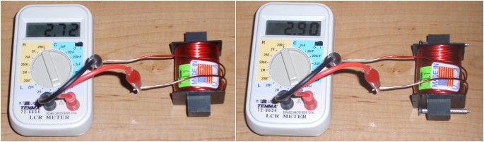
Effect of screws on inductance of Madisound steel laminate
Modeled response
Modeled on-axis frequency response
![[Image]](ZMV5-modeled-FR-individual.gif)
![[Image]](ZMV5-modeled-FR-reversenull.gif)
![[Image]](ZMV5-modeled-polar-vertical-1500-2000-2500.gif)
![[Image]](ZMV5-modeled-FR-offaxis-0-22-45.gif)
![[Image]](ZMV5-modeled-transferfunction.gif)
![[Image]](ZMV5-diffraction.gif)
The response curve is very smooth throughout most of the range. A mild bass rolloff has been designed into the vented system for a bit smoother in-room response considering the normal location of an average primary room node. The tweeter has a little raggedness at the top of the top octave, however it will be inaudible, even for those with young ears. This is because a deviation from flat response becomes less objectionable closer to the limits of audibility. It's the same concept that allows us to accept a typical system's ragged bass response in-room.
The MCM 55-3870 woofer has a very clean midrange, but merely average harmonic distortion on the low end. As such, the mild 2 dB rise in response was not selected as a baffle step consideration, it was a tonal balance consideration. A bit higher harmonic distortion in the bass combined with a flat response would give this speaker too much of a full or warm tonal balance. The mild rise compensates nicely for a traditional installation on stands in a medium size room. Use in a less than optimal situation, such as center channel or closer to boundaries will still need a larger cut in the BSC as shown in the options below.
The design axis is level with the tweeter. But, as you can see from the vertical polar response and the horizontal off-axis, it's practically the same anywhere in front of the speaker. It doesn't matter if the system is mounted horizontal or vertical, or if the listener is 45 degrees off axis in any direction. The only thing you get in extreme off-axis cases is a mild top octave roll-off due to the tweeter's diameter. The ability to hold the midrange response this well off axis is fully attributed to the tweeter's small flange allowing mounting close to the woofer combined with it's ability to cross over low.
There's nothing surprising in the transfer functions. Note the woofer circuit's series inductor interacting with the impedance peaks and effecting the low end response shape. This effect happens to all woofers with series inductors as small as 1mH, though very few folks measure their low end accurately enough to be able to see this. It will only show up in a good simulated anechoic bass response. It's hard to see in a curve that's full of ragged room effects or obscured by the mush of gating from a small window. We get a mild rise between 100-200 Hz thanks to the impedance slope on the high side of the upper peak, and a little droop at 60 Hz from the low side of the upper peak.
Measured response
Measured frequency response
![[Image]](ZMV5-measured-FR-raw.gif)
Measured response matches modeled response very well. This measurement is more of a confirmation that I didn't screw up my driver measurements or their phase information. It's also a quick check that my crossover components are within spec and properly connected. Raw in-box driver response curves show exactly what baffle edge diffraction and 2pi to 4pi baffle step transition are doing to the driver's infinite baffle response curves.
![[Image]](ZMV5-measured-HD.gif)
![[Image]](ZMV5-measured-HD+10.gif)
These drivers were individually tested for harmonic distortion in the test groups elsewhere on this web site. Those tests are done on an infinite baffle without any filter in place. It's enough for me to decide if drivers will work well together and what crossover frequency is optimal. The system harmonic distortion curve is a double check of that, with the drivers in their enclosure and the filters in place. An additional HD sweep 10 dB higher as been done, mainly for a look into tweeter low end limitations. This curve was done at a further distance to keep my mic preamp from overloading. As such, more room effects leak into the sweep, but it's still enough to see trends. Generally throughout the midrange the harmonic distortion does not increase at any abnormal rate, though the low end of the tweeter begins to show more tall order harmonics, and the bass distorts more partially from the lack of voice coil pole piece venting but mostly due to excursion limitations at this high test level. The tweeter increase is mild, so the real output limitation of this system is in the low end.
Power Handling
Modeled low end response in vented box with excursion @ 1,2,4,8,16,32,64,128 watts
![[Image]](ZMV5-powerhandling-LR4-100hz.gif)
![[Image]](ZMV5-powerhandling-LR4-150hz.gif)
If run full range, it only takes about 6 watts to drive the woofer into distortion at 75hz. The tonal balance is actually very listenable when run full range at low levels, but builders will want to seriously evaluate the need for a subwoofer when using this system. Adding a sub with an LR4 active crossover at 100 Hz drastically improves this system's overall sound quality not to mention the maximum output level. I'd consider a sub to be required for all but casual low level usage.
Output level improves quite a bit when moving the sub crossover up to 150 Hz, but at that point you'll have to have a pair of subs, one on each side near the mains, to prevent directionality from ruining the imaging. If you require extremely high listening levels, consider building this system as a tower with active subwoofers built right into the lower sides. A 150 Hz crossover is no problem then.
Enclosure
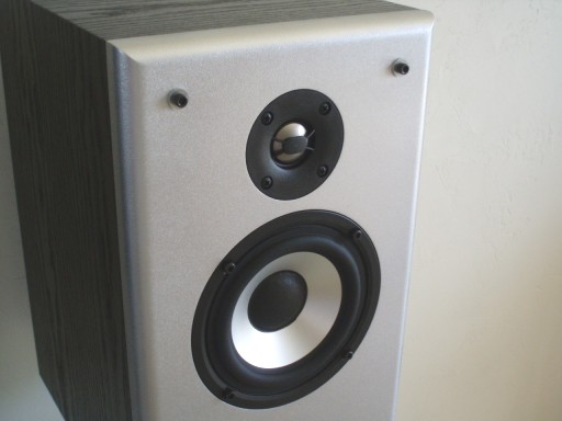
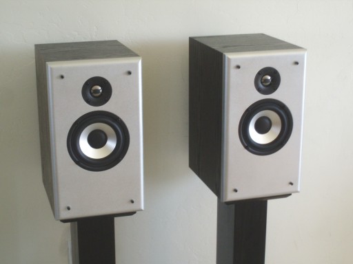
A good look at the beautiful "ZMV5" drivers
There is nothing too special about the cabinet. I built the pair shown here years ago and cheaped out with PE vinyl covering, but the enclosure is the same size as the .375 cu ft PE prefabs if you want to use them. The port is mounted on the back because that's where it was originally located when I first built these boxes. If you want, the port can be placed on the front below the woofer without any ill effects. If you do this, don't worry about midrange leakage. If you have good cabinet damping to keep reflections from bouncing around internally, it won't be a problem.
I used Sonic Barrier damping from PE throughout the cabinet, with .5" on the sides, 1" on the top and bottom, and 3-layer 1-1/4" on the back.
![[Image]](ZMV5-basstuning-infinitebaffle.gif)
![[Image]](ZMV5-basstuning-withbafflestep.gif)
The simple box model shows a bit of bass peaking with my chosen tuning, however the effect of baffle step counteracts all of the peaking. When the crossover is in place, the 70 Hz peaking in the model is reduced even more. Most simple box model programs ignore the effects of the filter and baffle step, but they are key to the design and shouldn't be ignored.
Options
![[Image]](ZMV5-options-R4.gif)
If the tweeter level seems to not match well with the woofer, one option is to adjust R4 to compensate for driver sensitivity variance. Be careful with this, as other issues may be easily mistaken for a tweeter sensitivity problem. I can say that it's fairly rare that the L-pad needs adjusting, but here's some options if needed.
![[Image]](ZMV5-options-reducedBSC.gif)
The default crossover is designed for stand mounting. If the system will be placed closer to boundaries, (and that may include center channel usage close to a TV or cabinet) a reduced baffle step compensation crossover may be used. This may help reduce a boominess problem if it shows up. I recommend construction of the default crossover first. Then if needed later, both woofer inductors could be unwound to the lower values, and a L-pad adjustment will bring the tweeter level up to match.
Room Placement
Like most of my designs, the best sound will be had from stand mounting, 1.5 to 2 feet out from the back wall, and a minimum of 2-3 feet out from the side wall. The height of the stand does not matter too much, but it will affect the frequency that the floor reflection happens. If you've got to place the speaker closer to boundary, you might need the reduced baffle step compensation crossover. Keep in mind however that sound quality takes a serious hit when there are early reflections.
Near field mounting is an option with these speakers, for example at a desk or mixing console. In that case, you'll definitely need a front mounted port below the woofer. The listening axis doesn't matter too much, but your biggest concern will be early reflections affecting the frequency response and imaging. Keep the speakers as high off the desk or mixing console as is practical.
I'm sure someone would ask why I made this design specifically adaptable to home theater, but I chose to use an unshielded woofer. The answer is simple: to discourage poor installations. Speakers should never be placed right up against a TV. At least a foot of space is recommended between the screen and the speaker, and more if you've got it. I don't recommend using center channels with TV's less than 40", so that rules out center channel placement near any old style glass picture tube. Plasma, DLP and LCD screens are not affected by magnetic fields, and floor standing rear projection TVs have over the screen as an option that does not require shielding. Will the shielded version of the woofer work in this design? I don't know, but probably not. I'm not going to bother with it. In a few years, shielded speakers will be a thing of the past.
Summary
Here we have a serious bang for the buck contender. These particular drivers are pretty much the best value to performance ratio in this price range. The only real shortcoming is the limited bass output capability, which can be resolved in most systems with good use of a subwoofer. If you do want a 5" 2-way system that does a better job without a subwoofer, you may want to consider another design, such as the ZD5 on this web site. At the time of this writing, a pair of ZMV5's will cost about $125 for drivers and crossover components. That, combined with a design that offers great sound while being is simple and flexible, makes it a winner.
Enjoy!
Page done by John "Zaph" Krutke © 2008
Also visit -Zaph|Audio-