Zaph|Audio - ZD5 - Scan Speak 15W8530K00 and Vifa XT25
ZD5 - Scan Speak 15W8530K00 and Vifa XT25
September 16, 2006 - Added "Designing this crossover"
June 20, 2009 - Added comments about tweeter level options
Introduction
Every good project starts out with extensive driver tests to aid in the driver selection process and to help mate drivers with complementary characteristics. Referring to my 5.5" test group and the Tweeter Mishmash, this project is made up of a couple of the best performers: The Scan Speak 15W8530K00 and the Vifa XT25TG30-04. Both are low distortion drivers with smooth and extended response that would appear to work well with a Linkwitz-Riley 2nd order crossover.
The coated version of the Scan Speak woofer performs better than the plain paper version. It's generally a little smoother and the breakup is controlled better. A Seas standard tweeter might have been a good choice, but the XT25 is just as good if crossed high enough, and it's easier to hit an LR2 target with a little more low end to shape. The Seas standards (like the 27TDFC and TBFCG) roll off a little too early for a LR2 crossover at the frequency I was shooting for.
These aren't the cheapest drivers in the world, so the emphasis for the project is performance over value. To the point, I expect this to be the highest performance 5" 2-way I've ever designed and also the most expensive. Still, it's not too expensive, and these drivers live up to their price while most other big dollar drivers are easily outperformed by Asian manufactured drivers at 1/4 the cost.
This project and article is not recommended for beginning DIY'ers.
Crossover
Crossover schematic for LR2 at 2400Hz
As you can see, I resisted simplifying this crossover in order to reach perfection regardless of cost. The woofer filter consists of a single inductor with 2 response shaping LCR notches, one series and one parallel. The tweeter filter consists of a single padding resistor (R0), 3 core response shaping components (C1, L2 and R3), a ladder delay network (L4, C6, C7 and L8) and an impedance flattening conjugate notch (C10, L11 and R12). R0 is used instead of a L-pad located after the filter, which has some tweaking benefits to be shown later. The XT25 is a tweeter without ferrofluid and it has a huge, sharp impedance peak. The conjugate notch is required. Without it, the tweeter will ring at the Fs, causing audible distortion. It's a little more obvious with an LR2 system. The XT25 is one of the most misused tweeters around because many choose to use it without a notch, and the shunt resistor in an L-pad often isn't enough to damp the peak. There's nothing too out of the ordinary about the crossover, except the appearance of the ladder delay network which doesn't seem to be used in other designs very often.
The ladder delay network is really the secret to this crossover. There are 3 passive solutions to the problem of mismatched acoustic center offsets common to LR2 designs. The first and most common is asymmetrical crossover slopes and the other common solution is using a slanted baffle. These work but are not optimal. Asymmetrical crossover slopes cause poor phase tracking around the crossover point which can remove a level of coherency depending on how severe the phase angles don't line up. (this is debatable and unproven however) There's no problem with crossovers that are mildly asymmetrical, but if you have to go more than one order in either direction on either slope, there can be some problems with the drivers not summing to flat. Slanted baffles represent a couple a different problems. First off, the drivers are off axis, which affects vertical off axis response and rolls off the top end response of both drivers. With the XT25, that's a big issue. Sure, using a 3/4" dome would solve the top end off axis issue, but I have not seen any acceptable 3/4" domes. The Hiquphon doesn't even come close to the performance required in a reference level design like this. Other 3/4" domes don't have the low end balls to pull off a LR2 crossover.
So, with all that in mind, you can see that the ladder delay network is the best solution in this system. It allows us to use a flat baffle, getting us the most out of the XT25's top end and giving us good phase tracking around the crossover point and symmetrical lobing when hitting LR2 targets perfectly.
![[Image]](ZD5-modeled-ladderdelayeffect.gif)
This circuit, as optimized does have a minor shaping effect on the response curve which hits LR2 dead on. In the image above, blue is the response with the delay network, and purple is without. But the primary effect is an 80 degree phase shift at the crossover point. The green phase curve is with the delay network and the red is without. In a no compromise design, the complexity and cost of this circuit is not a hindrance.
Don't forget that the tweeter's polarity is hooked up in reverse. And the schematic is accurate in that the tweeter does not directly connect to a ground. If you feel compelled to check and measure the reverse null depth, flip the woofer polarity, not the tweeter. The tweeter does not go 180 degrees out of phase if it's flipped.
The parts I recommend are as follows:
Eagle Metal Oxide Film for all resistors. Madisound medium bobbin standard air cores for all inductors except L14, which can be anything you want as long as it's DCR is .3 ohms or less. A Solen Perfect Lay 14 awg will do for L14, but a Sledgehammer Steel Laminate 15AWG will do even better for less money if you can unwind a 2.0mH to 1.8mH and have an LCR meter to confirm the value. Madisound can also unwind it for you for a small fee. Bennic Poly capacitors for all caps except for C10 and C20, which can be electrolytic. If you're afraid of using electrolytics, I recommend Solen Chateauroux Poly Fast Caps for C10 and C10. For C1, you will have to parallel a 1.0 and 3.3uF.
R12's value is listed as 4.7 ohms, but when you order it should probably be a 4.0 ohm, considering the series resistance of L11. That's what the green note means on the schematic.
Don't feel locked into these brands, they are just what I use myself. Whatever components you pick, don't get sucked into the snobbish audiophile hype regarding excessively expensive crossover components. This crossover doesn't have to cost $600 a pair, and you couldn't tell the difference if you did spend that much. The drivers are expensive because they do make a difference.
Designing this crossover
This section may only be of interest to folks using software to design and optimize crossovers.
For the woofer, I decided the two notches were required to reach my target response and slope in addition to the primary inductor which serves partially for baffle step compensation and partially for upper rolloff. One notch is series, one is parallel. The general guideline is that series notches should be used outside of a driver's bandwidth and parallel should be used within a driver's bandwidth. This insures the effectiveness of the notches and keeps the impedance from getting too low. The series RLC (17,18,19) is a broad low Q notch centered on about 5000Hz and the parallel RLC (20,21,22) is sharper Q at 950Hz. 6 components is a lot to add to a filter. I wrestled with this design to see if I could get what I wanted with fewer components, but in the end I decided that a few extra bucks isn't going to bother someone who blows $400+ on woofers.
For the tweeter, The first thing that's dropped into the circuit is the series notch to flatten the impedance. (10,11,12) The XT25 has harsh distortion at 500 hz, and without the notch, the impedance peak will cause a peak in the response at 500Hz when the rest of the filter is in place. Even if the peak was 40 dB down, the distortion is still wide bandwidth and audible when the right music fires up the resonance. Once I get the flat impedance, the rest of the filter can do it's job correctly and I don't touch the values again.
At this point, the tweeter filter topology is chosen and the primary components are placed in the tweeter filter. (0,1,2,3) We have decent looking individual driver response curves that look good but don't sum well due to the acoustic center difference. We currently have a mild null at the crossover point and vertical lobing that is asymmetrical. They are optimized to get somewhat close to LR2 regardless of the acoustic center mismatch with the woofer at the crossover point. The initial values here are not the final values, just something to work with and optimize.
![[Image]](ZD5-SEladdernetwork.gif)
A ladder delay network is also known as an all-pass network, lattice network or phase control circuit depending on who you talk to or where you look. For these 4 components, (4,6,7,8) I started with some very rough values using the calculator inside Soundeasy. Note that the equation used there is simplified and therefore relatively useless for determining final values. It's good enough for determining a starting point. A first order ladder was used because a 2nd order is too complicated and presents much more phase shift than I need.
A little experimentation shows that the most effective location for the delay network is after the filter.
![[Image]](ZD5-systemFRwithoutdelaynetwork.gif)
![[Image]](ZD5-optimizerworkingthedelayvalues.gif)
In the optimizer, I lock all values except for the delay network components. I set my frequency optimizing range and reference curve shape control to have the mild top end rise I wanted. I set the frequency / phase weighting to 80/20 along with the phase range and degree. Every situation may require different optimizer settings to get better results and unfortunately you're going to need experience and experimentation to figure out what your settings need to be. The optimizer then adjusts the values until the null flattens out and we have driver phase alignment. You can't have Soundeasy optimize too many components at once or the optimizer gets confused and the results go wild.
We're closer to done but not quite there. The rest of the optimization is done by hand. Changing values of individual components and then referring to the on axis response, vertical polar response, individual driver response and the reverse null shows us what the effects are. Move on to another component and repeat, revisting components as required. Reaching perfection from this point takes some time. After all the tweaking inside Soundeasy, some real listening may cause you to re-evaluate your design goals and head back to the drawing board. After some experience pushing out designs, the amount of real listening testing decreases as you learn how to reach your goals from within the initial design phase.
Overall, there was just not a lot of info out there about delay networks. In fact, there's not much info out there about the many ways to work the SE optimizer. Just remember that if the SE optimizer can't do it's job or is giving you wierd results, it probably means your over crossover topology needs to be changed. It's really not that hard though, and I was able to easily find something that works through experimentation with the SoundEasy software. Be aware that there are some simple equations to calculate ladder delay network values, but they don't work because they are far too simplified. Fo has to be shifted to match the needs of the rest of the circuit, impedance isn't flat and the circuit can affect the frequency response also. The only correct way to do it is within a modeling program such as Soundeasy, LSPcad or others where all affecting factors are considered.
Modeled response
Modeled response curve on the tweeter axis
![[Image]](ZD5-modeled-individualrolloffs.gif)
![[Image]](ZD5-modeled-revnull.gif)
![[Image]](ZD5-modeled-transferfunction.gif)
![[Image]](ZD5-modeled-polar-1400-blue-3400-red-200step.gif)
The response curve is respectably flat. Baffle step compensation is about 4dB which should be a good match for most rooms. The tonal balance is slightly tilted up in the top two octaves, which compensates for the XT25's slightly increased off axis rolloff when compared to other tweeters. Off axis plots will show this in more detail later.
I often hear designers say "I always tilt the response curve down." To that I say "I shape the response curve as required based on a balance of the audibility of distortion artifacts, the power response and the on axis response." Take note that always adhering to a certain on-axis response shape will result in a system design that sometimes works well. There is much more to it than what you see in an on-axis response curve.
The transfer functions are relatively smooth, and you can see the response shaping the filters provide. The reverse null is wide, symmetrical and deep which is a good sign of a nice LR2 design. But an even better sign of a good LR2 crossover is a vertical polar response that is smooth and symmetrical. I can tell you that is almost impossible to achieve what you see here in a flat baffle LR2 speaker without a ladder delay network. The design listening axis is ears level or slightly above the tweeter.
Measured response
Measured response and impedance compared with modeled
![[Image]](ZD5-measured-FR-IMP.gif)
![[Image]](ZD5-measured-FR-IMP-rawinbox.gif)
![[Image]](ZD5-measured-FR-offaxis-twinside.gif)
![[Image]](ZD5-measured-FR-offaxis-twoutside.gif)
![[Image]](ZD5-measuredimp-modeledimp.gif)
![[Image]](ZD5-measured-revnull.gif)
![[Image]](ZD5-measured-HD-system.gif)
![[Image]](ZD5-ratsnest.jpg)
The measured response is always a dose of reality compared to the modeled response. This tells me a couple of notable things. My R22 was slightly out of spec, showing up as a half dB difference at 900hz. More importantly, I didn't screw up or lose any of my phase information. That's the most common error that results in abnormalities in the crossover region. It was particularly important that I get it right with this design since it has an electrical solution to the acoustic center mismatch. Overall, I couldn't ask for a measured response to be any closer to the modeled response.
The measured off axis curves give you a little more insight into why I selected an on-axis response curve with a slight rise in the top two octaves. It flattens out almost perfectly a few degrees off axis. You don't have to have the tweeters pointing directly at you in this design. Generally it's not going to matter much if the tweeters go to the inside or outside, but I would lean towards tweeters to the inside. Off axis response through the crossover region is almost perfectly smooth.
The design enclosure is 14 liters (.5 cu ft) and the measured in-box woofer impedance shows up exactly as modeled. The only real difference is the top end of the impedance curve, since the model doesn't contain enough detail to properly predict the upper end of the impedance of a complex faraday shielded motor. Mainly, the model just has a simple Le rating when there's much more to it than that. Of course I use the measured impedance for designing, so no worries.
The system harmonic distortion plot is for reference only. It can not be directly compared to curves shown in my tests elsewhere because those are optimized for a testing of a single driver on an infinite baffle. But it does show distortion trends, and points out that there are no distortion issues in the crossover region, and the selected crossover frequency and slope was acceptable.
Bass tuning options
Vented tuning options in a .88 cu ft enclosure
![[Image]](ZD5-powerhandling-sealed.gif)
![[Image]](ZD5-powerhandling-vented.gif)
![[Image]](ZD5-powerhandling-sealed-LR4-80Hz-200W.gif)
![[Image]](ZD5-powerhandling-vented-LR4-80Hz-200W.gif)
The default design is .5 cu ft sealed, which results in an F3 of about 65 Hz. This is shown in most of the design plots on this page. The image directly above shows the vented options however. In a largish enclosure, we get ridiculously deep bass with the limiting max excursion happening around 50Hz with 30 watts. 15Hz above and below that, power handling increases dramatically. Running full range, don't expect to dump a lot of power into this design, or at least be a little careful if the music has a lot of content in the 50Hz area. A 50 to 100 watt amp is a good match for this speaker. The power handling images show excursion (the dashed brown line) at levels of 1, 2, 4, 8, 16, 32, 64 and 128.
Any sort of subwoofer crossover will allow you to dump as much power into this design as you want. A couple of 200 watt excursion plots with an 80Hz LR4 high pass offer ample evidence of that.
Often, large vented enclosures have severe lower midbass power handling deficiencies compared to sealed options. In this case with the recommended enclosures however, excursion is exceeded at roughly the same lower midbass frequencies. So if you've got the room to build the larger floor standing vented enclosure, you may as well do it as it offers more power handling in the 30-40 Hz range and most music doesn't have much content in the 20-30Hz range where the cone will unload.
Tweeter level options, and other options
Tweeter level options
I offer one option with the crossover, and that's tweeter level. Only one resistor value needs to change to do this, and it has the effect of modifying the upper end of the response without changing the lower end much. This is a tweak that will allow tuning to taste without messing up the phase coherency at the crossover frequency.
The default value is good if you don't want to toe in the speakers towards the listening area. If you do toe in however, you will probably want to reduce tweeter output a little bit. Get the extra resistors when you order your parts and don't be afraid to swap it out to see what suits you. This particular padding resistor location in the circuit was chosen over the more common 2 resistor L-pad before the tweeter because it makes tweaking so easy without messing with the response, phase or vertical lobing at the crossover point.
Note that subsequent tests of many XT25 tweeters have shown that newer versions are on average 1.3 dB more sensitive than the original version posted. If your tweeters are brand new, purchased from a vendor who has had new stock come in within the last year or so, you may wish to add a shunt resistor across the tweeter's terminals.
![[Image]](ZD5-tweetershunt-options.gif)
Using a shunt resistor equally reduces tweeter output at all of it's frequencies, a good option for newer versions of the XT25. It's also a good option for those who buy a pre-assembled crossover from madisound. No need to unsolder a resistor from the board, just hook up this resistor on the tweeter wire. Don't go smaller than 10 ohms, or other parts of the filter start to not work as well. So with this shunt resistor option, we have quite a bit of control over level and top end shaping.
With some of my designs, I post an add-on conjugate notch for impedance flattening. This might make a speaker friendlier to tube amps. This design however has a very low sensitivity and I recommend solid state amps only. Do not use this design with tube amps.
The amount of baffle step compensation in the design is fixed at 4dB and is not adjustable. This is mainly because changing the BSC affects the entire system crossover, and just about all parts would have to change. Therefore, I selected a common amount of BSC that is likely to work for most installations and locked it in. It should sound very balanced in small and medium sized rooms, and probably a little lean in very large rooms. If you do use these in a very large room, choose the higher bass tuning frequency noted above to help compensate.
Enclosure
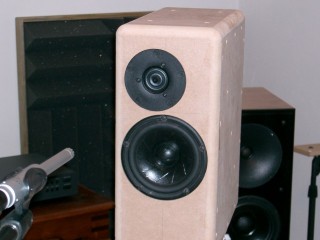
Test enclosure
Strict requirements if you want this system to sound good: Countersink all drivers, scallop the rear of the woofer opening for airflow with a 1/2" chamfer bit and round over the top and sides with a minimum of a 1/2" roundover bit. A 3/4" roundover bit is even better if your router can handle it. The driver locations are important, and the cabinet width must be 7.0". Varying from any of these design elements will make this system be less than the reference standard design it is meant to be.
The slim and compact front face helps the woofer maintain a very smooth response on it's top end by minimizing diffraction ripple. You can see this in the raw driver response curves. There are often debates about wide cabinets vs narrow. In the commercial arena, think along the lines of the Sonus Faber Stradivari vs the Audio Physic Virgo. The fact is that both of these are great cabinet designs because they keep the diffraction ripple out of the critical midrange. The Stradivari pushes it lower and smoothes it out with the wide rounded front. The Virgo pushes the ripple higher, and smoothes it out by effect of the ratio of driver width to cabinet width. Response above the baffle step becomes smoother as that ratio gets closer to 1. It's the cabinet sizes somewhere between these two that have a more ragged effect on the midrange response. In summary, you're best off if you pick either narrow or wide, but not somewhere in between. In this design, we chose a narrow enclosure.
The height of the vented design can vary based on your ear level. The bottom has an empty chamber, which can be filled with sand or just used to keep the crossover in. Otherwise, the crossover can just mount on the bottom of the main volume.
In the floor standing vented enclosure, as with all oblong enclosures, there should be some extra damping placed at the long ends to help absorb pressure nodes at frequencies where the wavelength is a related dimension.
Room Placement
Nothing too out of the ordinary here, and my recommendations are similar to most of my other systems. Keep the rear of the enclosure at least a foot out from the back wall and maybe 3 feet from the side wall. The woofer's three X, Y and Z room placement dimensions are from the floor, back wall and side wall. These should be as different as possible and not even multiples of each other for the smoothest in-room midbass response.
The speakers can be toed in slightly but do not have to be aimed directly at the listener. The option of toeing the speaker in a certain amount, along with adjustments of R0, should allow any listener to obtain their prefered top end extension and sparkle. In narrow rooms where placement closer to the side walls is closer than optimum, it may improve imaging to toe the speakers far in to a focal point a couple feet in front of the listener.
Summary
This system is a bit outside of my normal high value tendencies, but I would not have posted it if I did not think it offered some improvement over the average 5" 2-way design. This is without a doubt the best sounding 5" 2-way I've designed. I won't be so bold and arrogant to say this is the best 5" 2-way in the world, but I will say that I've seen enough overpriced speakers that just don't sound as good as their price might suggest mainly due to under performing drivers and poor design decisions.
Part of the magic of this system is simply due to the fact that it's a solid LR2 design. Accurate 2nd order slopes are hard to pull off, and only very wide bandwidth drivers with smooth response and low distortion need apply. Make no mistake that shallow slope crossovers sound better than steep slope crossovers. But doing shallow slopes right amounts to much, much more than just throwing a cap and coil on the tweeter and woofer. My Waveguide TMM design was more of a hardware solution addressing some typical LR2 design issues. This Scan Speak / Vifa system is more of an electrical solution.
In the end, an LR2 design has 180 degrees of phase wrap through the crossover while an LR4 has 360 degrees. The lower phase wrap directly equates to an improved midrange coherency. Honestly, most drivers and system designs require LR4 or greater slopes just to work properly. But when everything comes together for a LR2 system, it's the sweet spot in speaker design. Why is it the sweet spot? Because the next step is no crossover at all in a full range driver, which is a step backwards, introducing a whole different set of problems that detract from good sound.
If you are after value, this system is not for you. If you're after high performance music reproduction that is very uncolored and true to the original recording... and you have a few extra bucks to spend, you might consider this design.
Enjoy!
Page done by John "Zaph" Krutke © 2005
Also visit -Zaph|Audio-