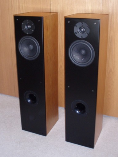
Zaph|Audio - ZRT - Revelator Tower
Zaph|Audio Revelator Tower"ZRT"
Introduction
This project is a cooperative effort between Zaph Audio and Madisound to develop a state of the art tower speaker using the Scan Speak 18W8531G Revelator woofer and the 6600 AirCirc tweeter. These are a couple of the best performing speakers at any price. They are not exactly cheap, but anyone building with these drivers can take comfort in knowing that they are getting the best that I've tested. See the driver comparison groups elsewhere on this web site to see how these particular drivers fare. This is a design that can be built at a cost that is a fraction of a typical commercial high end speaker of this level.
This project consists of 2 primary configurations, 2-way and 2.5-way. These will fit in the Madisound MD38T enclosure as single woofer vented configuration and two woofer sealed. Additionally, a 2.5-way vented is possible if you construct your own larger enclosure to accommodate the volume requirements. Many options abound. The primary option will be considered the 2-way in the Madisound MD38T enclosure, using a single 18W8531G and a 6600. This option will be fully described first with others addressed after.
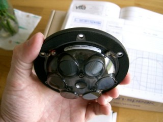
Rear view of the Scan Speak 6600 tweeter
This website is often hailed for low cost / high value designs. A design with drivers in the $200+ range seems to be outside of this tendency, but if the performance is there, the value is there on some level.
As a side note, this project is designed to work with 6600 tweeters no older than 2008. 6600's manufactured in 2006 and 2007 were different. I don't have a detailed record of production serial numbers, so the only way to insure compatibility in this design is to get the tweeters new from Madisound. Because of the early variations in tweeters, Madisound is taking sample measurements between batch restocking. This is an extra step to insure consistency with each new batch that arrives. If the 6600 changes, this design will be adjusted accordingly. So far to date in 2010, there have been no significant variations that would require a crossover update to the ZRT design.
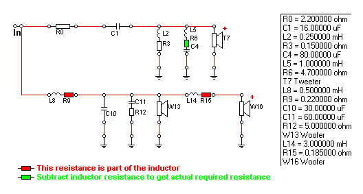
2-way crossover
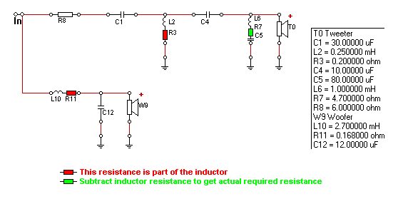
LR4 crossover at 1.7 kHz
This crossover is relatively simple with a low component count. It is functionally 4th order Linkwitz-Riley with a slightly shallower slope on the woofer to help with the acoustic center offset between the woofer and the tweeter. We have third order electrical on the tweeter and 2nd order electrical on the woofer to reach our target acoustic slopes. The tweeter uses a single padding resistor and also requires a conjugate impedance flattening notch across the terminals. A traditional L-pad would not have been enough to damp the tweeter's impedance peak and a LCR circuit will be needed with almost all 6600 applications to avoid ringing.
DCR is kept low in the primary woofer series inductor with the use of a heavy gauge steel laminate Sledgehammer. If assembling your own crossovers, be sure to not mount these with screws through the holes on the end. If you do, buy a Sledgehammer about .3 mH lower, as the screws will increase the inductor value.
The 80uF cap in the tweeter notch could be an expensive component. I would have no issue using an electrolytic for that to keep cost down. I feel that the audible difference is not big enough to spend more, if it's even audible at all. But I will concede that most will not want an electrolytic cap in a design of this level. I'm not a "capacitor psycho", so I've got no problem with it. The Madisound kit will not contain any electrolytics, but they did at least offer a cheaper cap in the tweeter notch to keep the cost down. There will be a "high end" version available also but honestly, the cost of that crossover is still relatively small compared to the drivers.
2-way modeled response
Modeled on-axis frequency response
![[Image]](ZRT-2way-modeled-FR-individual.gif)
![[Image]](ZRT-2way-modeled-FR-revnull.gif)
![[Image]](ZRT-2way-modeled-polar-1000-blue-2400-red-200step.gif)
![[Image]](ZRT-2way-modeled-transferfunctions.gif)
These drivers are very well behaved and were relatively easy to work with. With their low distortion, a flat response gives us a neutral tonal balance that sounds great with no listening fatigue. The reverse null is deep, showing us that this is a traditional Linkwitz-Riley design. The low crossover point gives us a broad vertical listening window with good symmetry. The transfer functions are smooth with good tolerance to component variation. The design axis is ears level with the tweeter, and all plots are at 1 meter.
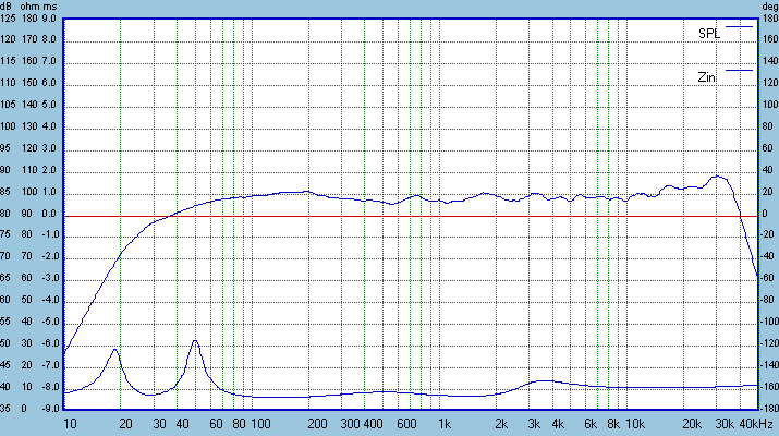
The impedance curve is relatively benign and should work well enough with tube amplifiers. Impedance for this 2-way version stays above 6.5 ohms, averages 8 ohms through most of it's range and does not exceed 14 ohms above the bass tuning peaks. No additional impedance control circuitry is needed.
2-way measured response
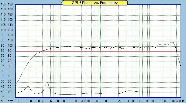
Measured frequency response on-axis, 10ms window
![[Image]](ZRT-2way-measured-FR-offaxis.gif)
![[Image]](ZRT-2way-measured-FR-rawinbox.gif)
![[Image]](ZRT-2way-measured-FR-revnull.gif)
![[Image]](ZRT-2way-measured-HD.gif)
![[Image]](ZRT-2way-measured-port-nearfield.gif)
Actual measured response is very close to the modeled with the biggest difference being in the 400-500 Hz range. Seeing as the impedance curve with the crossover in place is exactly the same as the modeled curve, this is likely due to a mild difference between the individual driver measurements used in the model, and the system response curve. The model uses on-axis data with piston based off-axis simulation for a given mic location, while the actual measured system response is real. The mic location for the woofer response used in the model is 6" lower that the mic location used in the measured system response. Some floor bounce still comes through a bit in the nearfield woofer plots with diffraction added. This floor bounce is at a mildly different frequency and level for the measured system response compared to the driver curves taken for modeling, and the difference presents itself in the 400-500 Hz range. This is more than anyone wants to know, but I like to have a perfect grasp on differences between modeled and measured - even if it's only 1dB.
The system harmonic distortion sweep was done in-box at a further distance than my standard infinite baffle tests to allow proper summing between the tweeter and woofer. As such, the plot is not directly comparable to others on this site, but it does show trending between the drivers. The system is clean throughout it's entire useful range, but it is exceptionally clean in the bottom of the tweeter's range.
There are often some concerns about mounting a port on the front baffle. I used to believe the concerns myself. I often mount my ports on the back, but now this is more for baffle space considerations than midrange leakage or organ pipe resonances. I found that the midrange leakage of front mounted ports, particularly these flared ports, low enough to make front mounting an acceptable option. Above I show a near field port measurement. While not exactly smooth a couple octaves above tuning, there isn't much peaking to worry about and the raggedness is off the audible radar. An item of concern for measuring front mount ports is output from the woofer leaking into the nearfield port measurement, combining out of phase at some frequencies and causing additional raggedness. Some of this can be seen in the plot above. It's impossible to differentiate between midrange leakage though the port and interfering output from the woofer on the outside of the baffle. I'm not sure it matters anyway.
18W8531G Power Handling
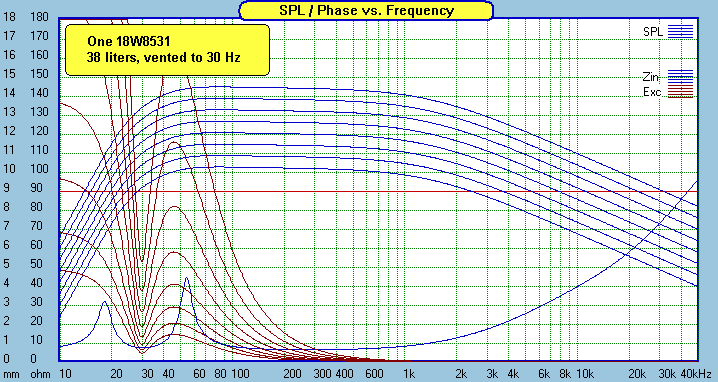
Excursion vs SPL, full range, vented, 1,2,4,8,16,32,64,128 watts
![[Image]](ZRT-2way-38liter-powerhandling-LR4-80Hz-200W.gif)
Run full range, linear excursion in the vented enclosure is exceeded with about 30 watts. Be aware that the 18W8531G and most other Scan Speak drivers overload gradually and are capable of quite a bit more excursion than their Xmax spec may suggest, before distortion becomes objectionable. With an 80 Hz LR4 sub filter, excursion is exceeded at 85Hz with a few hundred watts. Realistically, I'd expect thermal and compression issues to show up well below that. A 50-100 watt amplifier should be a good match for this. These speakers have decent sensitivity, so a person with a low power amp could be made happy.
2-way enclosure
The "ZRT" in a Madisound MD38T enclosure
![[Image]](ZRT-2way-38liter-(1)8531-ventedtuning.gif)
![[Image]](ZRT-2way-inbox-impedance-medstuffing-bot.gif)
![[Image]](ZRT-2way-inbox-impedance-heavystuffing-bot.gif)
The tweeter location in this design is centered for manufacturability and the distance from the top was selected for a decent diffraction signature with a centered tweeter. Tuning calculations were done with T/S parameters that were averaged from 8 woofers. Qts averaged a little higher than spec, and it works out well using the full volume of the MD38T enclosure. Bass extension is extremely deep with a single vented 18W8531 in this box. My preference is the 30 Hz tuning, which gives a mild rolloff with good extension that seems to blend well with a typical room response.
I call for heavy stuffing at the bottom of the enclosure to reduce the lengthwise pressure node at 140Hz. Not doing so would cause some audible raggedness in the midbass. The difference between enough and not enough stuffing is easily seen in an impedance curve.
2-way options
![[Image]](ZRT-2way-modeled-options-R8.gif)
Tweeter level is relatively easy to adjust to accommodate taste and manufacture SPL variance, however minor that may be with Scan Speak drivers. Get some extra resistors - level tweaking is recommended.
![[Image]](ZRT-2way-modeled-options-L10.gif)
This L10 inductor change, along with a change of R8 to 5 or 6 ohms will bring up the midrange to help with less than optimal placement. You may consider this mod if your room is too small, your speakers are too close to the walls, or you are listening in more of a nearfield situation. I recommend the default inductor first, as that will be best for most people, and then tweak from there as needed. If you can measure inductance, you can unwind the 2.7 to something lower. Just be sure to keep the wire tensioned and tightly replace the tape holding it in place. A loose wound inductor can cause distortion.
The default design is the one that sounded best to me in my listening room, but not everyone has a similar room or similar tonal balance preferences. This design is intentionally easy to tweak, so don't be at all afraid to try new values, even if you're just curious how it will change the sound. It's relatively easy to swap components, provided you didn't glue the baffle on or glue the crossover to the bottom.
The 2-way design can easily work in a stand mount enclosure sealed of reasonable volume. The MD20 is perfect for that.
2.5-way design option
![[Image]](ZRT-2.5way-38liter-(2)8531-sealedtuning.gif)
![[Image]](ZRT-2.5way-65liter-(2)8531-ventedtuning.gif)
This 2.5-way design would work well sealed in the MD38T enclosure or a custom built vented enclosure of larger volume. The sealed bass extension of the 18W8531 woofer is surprisingly satisfying in 19 liters, which is half of the MD38T enclosure. In the sealed MD38T, the lower woofer can be located below the halfway point so that the grill can be put on without the center crossmember hitting the woofer frame or surround. This configuration is what I built, modeled and listened to. If you aren't going to use the grills, the lower woofer could be mounted close to the upper woofer with your own cuts in the blank baffle.
The 2.5-way crossover design is a cascaded configuration, with the lower woofer's baffle step compensation inductor placed between the woofers and the rest of the components effectively filtering both woofers. The crossover is close to a 3rd order configuration, and as such there is no reverse null. The individual driver rolloffs are close to 3dB down at the crossover point rather than the 6dB down that is a characteristic of Linkwitz-Riley crossovers. More discussion on this below.
![[Image]](ZRT-2.5way-modeled-FR.gif)
![[Image]](ZRT-2.5way-modeled-FR-individual.gif)
![[Image]](ZRT-2.5way-modeled-transferfunctions.gif)
![[Image]](ZRT-2.5way-modeled-polar-750-blue-2500-red-250step.gif)
A 2.5-way system is by nature a full baffle step compensation design. This design in particular requires a large room and at least 2 or 2.5 meters listening distance for the best summing between drivers. The modeled mic location is on the tweeter's axis and 2.5 meters distance, though I've verified good frequency response as close as 2 meters. At one meter, the response gets ragged due to the relative distance from the mic/ear to the lower woofer and the tweeter. The vertical polar response shows this design's 3rd order tendencies which favors on or above axis. Power response will be very smooth. The weak point in this and most 2.5 way designs is the lower woofer causing a droop in response above the axis. See the blue 750 Hz lobing for example. This is minimized either by mounting the woofers close together, or by maintaining a further minimum listening distance which is what this design calls for. There is a sole benefit of having the lower woofer spaced down a bit - a reduction in the floor bounce reflection. The two woofers have different floor reflection frequencies resulting in a smoother in-room response. Typical floor bounce is 300-400 Hz, thought it's not completely smoothed out with the lower woofer already starting to roll off.
![[Image]](ZRT-polar-750-lowerwooferposition.gif)
If a builder of the 2.5 way chooses to mount the lower woofer right below the upper woofer, there will be a mild improvement in the vertical lobing centered on about 750 Hz. This is shown above, as 3dB less droop about 20 degrees above axis. The on-axis effect at 2+ meters is minimal however with only a change in the power response having a barely audible effect in-room. Which is better? It comes down to choosing better upper midrange response above axis with one or lower high midbass floor reflection with the other. Your choice.
![[Image]](ZRT-2.5way-measured-FR-nearfield-sealed.gif)
![[Image]](ZRT-2.5way-measured-FR-inroom-2.5m.gif)
A near field bass response of the woofer shows just how low the sealed enclosure goes. Not bad for a 7" woofer. Getting a useful anechoic response curve with a mic at 2.5 meters is just about impossible in a home environment, but a room response curve is certainly easy to do. (and often a dose of reality) A typical room response curve will always have a primary dip and peak corresponding to the room's largest dimension. This plot is no exception. Other than that however, it stays within a 5dB window for most of the response and tonal balance is excellent to my ears.
Summary
This is about as good as it gets for a 7" 2-way or 2.5-way. Not exactly cheap, but about as high performance as anyone could hope for. When the drivers like this have incredibly low distortion, and the design is well implemented, you get a non-fatiguing "listen all day" type of sound.
Enjoy!
Page done by John "Zaph" Krutke © 2008
Also visit -Zaph|Audio-