Zaph|Audio - 4
Zaph|Audio 4" Bargain Mini"ZBM4"
July 7, 2008 - Note: the Aura NT1 tweeter is now available again at Madisound. Word to the wise: get a couple extras.
Introduction
This system is intended for someone who needs a bit more power handling and low end extension than a typical 3" fullrange system can provide, along with a smoother top octave and better off axis response. System cost is just under $40 per speaker for drivers and crossover components. That's not exactly cheap considering the cost of mass production minispeakers at the typical big-box retail outlet, but sound quality is almost always poor in those speakers. In fact, there's a general public mindset that if you buy cheap and small speakers, you don't care about sound quality - only size and price. This system is intended to be small and inexpensive, but sound quality is goal number one.
It seems like there's not nearly as many 4" woofers available as there are 5-1/2" or 7". The selection is a bit smaller. The search has been on for quite some time for the drivers to construct a great sounding, high value, very small 2 way system. The MCM 55-1853 woofer ($13) and the Aura NT1 tweeter ($9) were perfect candidates. Both are relatively low distortion, smooth, and most importantly inexpensive. The previous Audax Mini system on this web site sounded good, but Audax was a bit overpriced and they pulled out of the DIY market anyway. I wanted to come up with something that sounded better but cost less - no small feat. I think I've succeeded with this system.
Crossover

LR4 crossover at 3 kHz
The crossover is an acoustic 4th order at 3kHz, slightly asymmetrical to tilt the listening axis down in line with the tweeter. To reach that target, 3rd order electrical plus an L-pad was used on the tweeter, and 2nd order electrical was used on the woofer. The deviation from slope symmetry favored both a steeper slope on the tweeter and a milder slope on the woofer, though there is good symmetry about a half octave on either side of the Fc. This is somewhat common for LR4 systems with cone midwoofers and their related acoustic center setback. The natural responses seemed to work best with this arrangement, not to mention that power handling on the low end of the tweeter became a non-issue. The woofer did have some breakup but not enough to require extra components thrown at the crossover.
With the high crossover point, most components are small values and relatively cheap. Here's the component list from Madisound:
I'm not a big fan of expensive boutique crossover components, but I don't think anyone is going to go all out on components with drivers of this price range. No need to talk anyone out of foil inductors or metalized film and foil caps this time around. It's optional to get a few extra resistors of various values in case you need to tweak anything. More on that in the options section below.
Modeled response
Modeled on-axis frequency response
![[Image]](ZBM4-modeled-individual.gif)
![[Image]](ZBM4-modeled-revnull.gif)
![[Image]](ZBM4-modeled-transferfunction.gif)
![[Image]](ZBM4-modeled-polar-2200green-3800red-200step.gif)
Response is very smooth with a mild rise in the upper midrange and treble. The amount of baffle step compensation is roughly 4 dB as shown and is a pretty good tonal balance in most rooms when mounted on stands a foot or two away from the rear wall. The individual drivers exhibit Linkwitz Riley behaviour, both being 6 dB down at the crossover point and summing to flat. The reverse null is taken on the tweeter axis and shows exactly where the crossover point is. It's depth shows how well the phase aligns at that point. The transfer functions show smooth filter behaviour. There are no notches in this design and none were needed since the woofer's breakup node is relatively benign. A notch was nearly required on the low end of the tweeter due to it's high Qts bump, but a 3 pole filter with a low Q was able to massage it into shape.
The vertical polar response of this system was modeled on the tweeter axis. It's symmetric and relatively tall. No "head in a vice" listening position is required with these speakers. High crossover points don't really work well unless the drivers are small enough to allow close spacing. This tiny rear mount tweeter certainly helps in that regard. That's not to say high crossover points with large drivers can't work at all, they just severely limit your listening position and affect the power response enough that the in-room sound can be a little hard to get right. If a full size flanged tweeter is used with a 3kHz crossover, the vertical listening window could be as small as a couple inches. With this system, you can get as much as 20 degrees vertically off the tweeter axis before a null starts to become audible, and the null fully reaches it's depth at 45 degrees.
Thanks to the small drivers, horizontal off axis for this system (not shown) is so good that nothing really happens until you get 45 degrees off axis, and even then it's only a couple dB down in the top octave.
Measured response
Measured frequency response
![[Image]](ZBM4-measured-modeled-response.gif)
![[Image]](ZBM4-measured-individual.gif)
![[Image]](ZBM4-measured-revnull.gif)
![[Image]](ZBM4-measured-raw-inbox.gif)
Measured response matches modeled response very well for the combined, individual and reverse null curves. These measurements are more of a confirmation that I didn't screw up my driver measurements or their phase information. It's also a quick check that my crossover components are within spec and properly connected. Raw in-box driver response curves show exactly what baffle edge diffraction and 2pi to 4pi baffle step transition are doing to the driver's infinite baffle response curves.
![[Image]](ZBM4-measured-HD-system.gif)
These drivers were individually tested for harmonic distortion in the test groups elsewhere on this web site. Those tests are done on an infinite baffle without any filter in place. It's enough for me to decide if drivers will work well together and what crossover frequency is optimal. The system harmonic distortion curve is a double check of that, with the drivers in their enclosure and the filters in place. Most importantly, the filter tames the woofer's rising 3rd order harmonic distortion peak, and reduces much of it's high end tall order distortion also. 3kHz does indeed work well for this woofer.
Power Handling
Modeled low end response in vented box with excursion @ 1,2,4,8,16,32,64,128 watts
![[Image]](ZBM4-powerhandling-sealed-fullrange.gif)
![[Image]](ZBM4-powerhandling-vented-LR4-100hz.gif)
![[Image]](ZBM4-powerhandling-vented-LR4-150hz.gif)
If run full range, all it takes is about 10 watts to drive the woofer into distortion at 70 to 80hz. These speakers actually sound pretty good when run full range, with low end distortion that's not nearly as bad as 3" woofers. Just don't have any unreasonable expectations about their output capability and bass cleanliness when not actively crossed over to a sub.
Now if you do need more output, you will need a subwoofer and the two LR4 power handling charts should help you select an initial crossover frequency. After that, let your ears do the tweaking. If low bass content seems to cause mid bass grunge from the minispeakers, your sub crossover frequency is likely too low for your preferred listening level.
I have to say, using these with a good sub and an active sub crossover sure does clean up the midrange quality a bit. Sure, the low end sounds ok all by itself, but expect to be blown away when you compare that to what you might get with a Dayton RS subwoofer for example.
Beyond about 100 watts, going higher with a sub crossover point isn't going to help the system get louder. You'll start hearing signal compression and thermal power handling becomes the main issue. That should give you a rough estimate of this system's capabilities.
Enclosure
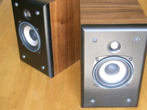
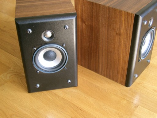
The "ZBM4" in a dramatic angled view
![[Image]](ZBM4-baffleback.jpg)
![[Image]](ZBM4-insulation.jpg)
The great thing about small enclosures is that they are so easy to cut and work with. A quarter sheet of MDF will likely be enough if you lay out the parts ahead of time. The back side of the woofer cutout has a chamfer going all the way around for airflow. The tweeter is a rear mount design intended for 12mm material. In this 3/4" baffle, I cut the hole then did a rabbet around the inside edge to get the right depth. If you get the initial hole just the right size, you can even press fit the tweeter into place like I did. (with a bit of glue) On the other hand, this titanium dome tweeter is easily damaged. If there are children in the house, you'd better make the tweeter easily replaced.
The tweeter will fit into a 36mm hole. It's an odd size. A 1-3/8" bit will be too small while a 1-1/2" bit will be too large. There are some 35mm bits available that will work with a tiny bit of sanding on the inside edge. I routered mine with a modified Seas circle jig. The jasper jig won't cut a hole this small but you could always make your own circle jig with a simple 1/4" board and a well placed nail. There are 35mm Forstner bits available, which seems to be a sort of standard for small clock inserts. That might be how the original tweeter designers came up with this odd dimension. Finding a way to cut the right size hole could be the most difficult thing about this design. Do the tweeter hole first and practice at it if you have to. The rest of the building will be easy in comparison.
I have to admit, this woofer's frame is not a very good design. It's somewhat flimsy and prone to damage if the screws are torqued hard enough. It's also prone to leakage if the hole is not cut just right. If you look at the frame from the side, you'll see a stepped portion. You can make the woofer hole big enough to avoid a countersink, but then you will have to be very careful to get it just the right size - it's easy to make it 1/16" too big, and then you'll have leakage at the flat part of the frame. If you make the hole smaller, you will also need a small countersink for the step to allow the frame to sit flat on the baffle. All things considered, I'd rather have a better stamped frame in much the same way the Parts Express DA175 improves upon the MCM 55-1860. I'd even pay a few bucks extra to get a cast frame, but for this performance, I'll take what I can get.
Screw the woofer in very lightly. Once it's held into place, seal the woofer from the back with a fillet of glue. Obviously, this is assuming a removeable baffle, something I think everyone should do. If you screw up, just make another baffle. And when that speaker has lived it's life, just put another in. A simple bead of Elmers will work, but something non-hardening would be even better. This will not only prevent air leakage, but it will also prevent the frame from vibrating on the baffle.
The damping/absorbtion material I used was Parts Express Sonic Barrier. Thick 1-1/4" 3 layer on the back and top, 1/2" single layer on the sides and bottom. I recommend Sonic Barrier or Whispermat. I use either on various projects. I just used a hole saw and made quick holes for the terminals and port tube. The port tube was 1" x 3.375" and the terminals were Yung 5-way binding posts from Madisound.
![[Image]](ZBM4-modeled-boxresponse-vented.gif)
![[Image]](ZBM4-modeled-boxresponse-sealed.gif)
Sealed may be the best option suited to those placing the speaker close to a boundary or in a smallish listening room. Of course this will reduce the low end extension, but it also will reduce the 100-200hz output enough to remove some midbass emphasis if that happens to be a problem. See the options and room placement section below for more information. I'd advise building with the port, but plugging it from the inside if needed. You can buy a slick looking black rubber port plug at Home Depot. They seem intended for drains but fit ports perfectly. You can always unplug it if you move the speakers to a more suitable location.
Options
![[Image]](ZBM4-modeled-options-lpad.gif)
If the tweeter level seems to not match well with the woofer, one option is to adjust the L-pad to compensate for driver sensitivity variance. Be careful with this, as other issues may be easily mistaken for a tweeter sensitivity problem. I can say that it's fairly rare the the L-pad needs adjusting, but here's some options if needed.
![[Image]](ZBM4-modeled-options-BSC.gif)
The default crossover is designed for stand mounting. If the system will be placed closer to boundaries, a reduced baffle step compensation crossover may be used. This may help reduce a boominess problem if it shows up. I recommend construction of the default crossover first. Then if needed later, the primary woofer inductor could be unwound to the lower value, and a L-pad adjustment will bring the tweeter level up to match.
![[Image]](ZBM4-modeled-options-flatimpedance.gif)
Any decent solid state amplifier will be able to deal with the impedance peak in the default design. If using tubes however, that impedance will need to be flattened out with 3 extra components as shown in this circuit. Tubes aren't really recommended with this design because of it's relatively low sensitivity, but the option for flat impedance is available if anyone wishes to use it. It's not necessary for a solid state amplifier.
![[Image]](ZBM4-modeled-options-L7dcr.gif)
The default DCR value of the series inductor is chosen with budget in mind. These plots show you what you can expect to gain by going with a more expensive lower DCR inductor. Essentially, you get a little more midbass output. If you find midbass output lacking with the original inductor, upgrading to a low DCR inductor may help. Consider a heavy gauge steel laminate core to keep the price down along with the DCR.
![[Image]](ZBM4-FR-55-3853.gif)
The 55-3853 woofer is very similar to the 1853, but with a cast frame and a slightly different response curve. It's still close enough that it can be dropped into this design. It has the same bolt pattern and cutout. The cast frame is a large improvement, but it costs a few bucks more per woofer. If you're putting together a 5.1 or 7.1 system, the cost difference could be substantial.
Room Placement
The best sound will be had from stand mounting, 1.5 to 2 feet out from the back wall, and a minimum of 2-3 feet out from the side wall. There are plenty of well built "surround" stands on the market, just pick one. Preferably, pick a stand that keeps the tweeter at ear level, but you do have some flexibility in this regard.
The real problem with speakers this small is that people will be tempted to mount them on a wall or place them on a bookshelf or end table. Yes, that is possible, and the alternative reduced BSC crossover version will probably work better in that case. Just be aware that it is non-optimal and early reflections from nearby boundaries or objects will take a serious bite out of the sound quality. If that's your only placement option, then go for it. Just realize that the speakers are not sounding as good as they could be. This will be true for any speaker placed near a boundary or object.
Near field mounting is an option with these speakers, for example at a desk or mixing console. A front mounted port below the woofer might be a better idea than rear mounting in that case. The listening axis should be ear level with the tweeter, and the speakers should be elevated off the desk or the console to avoid that reflection. A little set of miniature stands might be a good idea.
Summary
This system represents a very good value, and performs excellently regardless of price. Small, smooth and clean sum it up nicely. On the negative side, there are really only two issues: output is severely limited when running full range and driver mounting is somewhat difficult. If you can live and work with those issues, this system won't disappoint. It won't make you go broke either. You could put together a 5 piece system for $200 plus building materials. Sure, you could run over to Best Buy and grab some cheap mass production crap off the shelf, but you'll get what you pay for. For example, these mini speakers sound far better than the popular Insignia coaxials anywhere above 100hz. When sound quality is important, Do It Yourself. Start small if you have to.
Enjoy!
Page done by John "Zaph" Krutke © 2007
Also visit -Zaph|Audio-