Zaph|Audio
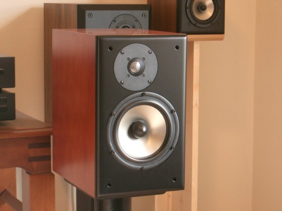
Seas L18 / Seas 27TBFCG
11/20/04 - A few changes and additions
01/17/06 - Response shaping options
07/07/07 - Removed some vague subjectivism
Introduction
I love Seas metal cone drivers, and have used just about all of them in some form or another, but up until now I would not use one larger than 5" in a 2 way. The reason being that the breakup node would be too low for the driver to be of use in a 2-way. (more on this below) The L15 was a great in a 2-way but the L18 H1142 and H1085 versions had the breakup node in the region of 4kHz to 5Khz. A while back, I saw that the Seas web site listed a new version of the L18, the H1224. The breakup node was now at 7kHz and the H1142 had been discontinued. It took a while, and I was looking for the H1224 for a long time, but Madisound finally got them in stock and I grabbed a couple of them.
Bjorn Idland, Lab Technician at Seas, explained the difference one day on the Madisound forum: "The H1142 is the first version of the L18. This driver has a straight cone-profile and it use the surround similar to the P17 (but of course in a low-loss material). We wanted to make a new version and found a new curved cone profile using Peter Larsen's FineCone FEM modelling software. As the measurements show, the breakup peak is now pushed higher in frequency. The new version (H1224) also use the same surround as the W18. Both are good drivers, but some might find it easier to implement the H1224 in a 2-way system."
A study using the software Bjorn is referring to can be found here: Geometrical Stiffness of Loudspeaker Cones. Very cool stuff.
The Seas L series woofers can be considered the poor man's Excel. They are less than half the price, with 95% of the performance. In some cases, the performance is even improved, but the core design difference between the standard line L series and the Excel line W series is the lack of copper in the motor assembly. The L series drivers lack the faraday rings, and as a result have slightly higher distortion and higher inductance in their operating range. Don't let that fool you however, the L series drivers represent incredible value and performance.
The Seas 27TB series tweeters are an aluminum tweeter based on the same motor used in the fabric dome versions. I chose the "TBFCG" version, which has ferrofluid and a rear chamber. I had previous experience with this tweeter and found it to be pretty much the best tweeter in the $30 class. Don't let the slightly rolled off top octave fool you... this tweeter will have all the "air", "sparkle" and [insert audiophile verbage here] that you'll ever need. But the best thing about it is its smooth response, low distortion and low frequency power handling ability.
Overall, I don't think you can get better drivers for anywhere near these prices.
Crossover
Crossover
The crossover is around 2000Hz, 4th order Linkwitz Riley. This is a topology that works well for many metal cone drivers, provided there is not a large breakup node lower in frequency than the main breakup node. The L18 does ok in this respect, while some other aluminum cones do not. Having the main breakup node at 7kHz or 9kHz does not help you much if there is another one at 4Khz. The big inductor is a steel laminate with a low DCR. I got it off the Madisound sale page for about $2. (get them while they last, it's a big money saver) For capacitors, I used exclusively Bennic Polys. For resistors, I used Eagle metal films. I don't believe in big dollar crossover components. Spend your money where it makes a bigger difference. There's a good amount of flexibility in the DCR for inductors L3 and L7, but try to keep L0 below .4 ohms to avoid affecting the woofer SPL too much.
This crossover has about 5 dB of baffle step compensation. It looks like more on the transfer function plots, but it's misleading with the crossover point so low due to the rolloff starting as low as 1kHz.
I've included images of my crossover boards. I like things tidy. For me, that meant lining components up on the front side, and using bus wire for jumpers on the back side. I used a single board for both the woofer and tweeter sections, but I located the tweeter coil at the far end of the board to avoid electromagnetic interaction. The big steel laminate inductor has screw holes that are handy for bolting it in place, and the others are epoxied. I mounted the board on the side, near the back.
There were several versions before I arrived at LR4 @ 2kHz. Of them, I came up with a couple LR2 crossovers at about 1.8kHz. One required either the woofer on top or a slanted baffle, and the other had a trellis delay network and a complexity of so many components that it was ridiculous. LR2 did sound good, and possibly a small bit better than LR4, but given the low crossover point requirements I believe the tweeter was straining under high output. All things considered, I think LR4 at 2Khz is the best choice for this combination. We get good power handling, simplicity and a good listening axis angle on a flat baffle. After busting my noggin on 2nd order attempts, I began to feel like metal drivers are simply meant to be 4th order.
The single notch is a precision strike on the main 7kHz peak, and greatly reduces most of the garbage peaks above it. I would call this a "bottomless" notch due to the lack of resistor in the circuit. The only resistance is in the inductor. Notches of this nature are inherently high Q and deep, but it still took some tweaking of the values to position the notch correctly and still help out with the woofer's required rolloff.
I did create a reduced baffle step crossover. However, I've decided not to distribute it, as it encourages poor installations in rooms that are too small or placement too close to the wall.
Modeled response - @1M, on tweeter axis
Modeled response
The design axis for this project is ears level with the tweeter, or slightly above. On paper (or on screen) the notch completely kills all breakup. In reality, it doesn't quite work as well as on paper, but still effective enough. The vertical off axis chart is a good estimation of the vertical listening window. Vertically +30/-20 degrees will still result in flat response, by +40/-30 the null has shown up and by +50/-40 degrees the tweeter is completely out of phase with the woofer. The vertical window is by design very tall. This is not a speaker that will lose any of it's midrange when you stand up, and the midrange floor reflection at a typical listening position is reduced from the -40 degree null. It works out well.
Measured Response - @1M, on tweeter axis, 4ms window
Measured response
On to reality. Measured response matches modeled response fairly close. As mentioned above, the notch does not take the extra high frequency garbage out as much as expected, but it's still 30 dB down and essentially off the radar. Channel matching showed good matching between drivers, with some of the minor differences attributed to component value variation. The various off axis curves show excellent power response. Tweeters to the outside with ears slightly above the tweeter axis will give the smoothest response. See below for suggested listening room arrangements.
The design listening axis was the tweeter, but the in-phase listening axis came out to be a few inches higher than that at the listening chair. This is ok in my book. Had the listening axis moved downward, I would have had to start over and go to work on matching the acoustic centers. One of my goals for this project was to avoid a woofer on top or slanted baffle layout, so this listening axis works in my favor. In a typical listening position, the best phase matching between woofer and tweeter happens with your ears level with the top of the enclosure, but given the tall vertical window this design provides, it's not going to matter much where you are in the room.
L18 near field THD, measured near outside of cone
Distortion
Nothing too surprising about the CSD. The cone rings like the liberty bell at 7Khz but is well behaved in the midrange. This driver's THD is what makes it special. Other drivers like the old L18 and the current Excel W18 have the breakup node in the 4-5kHz range. Observe the W18 distortion plot in the lower right corner of this spec sheet. A breakup node of 4.2kHz directly correlates to a peak in 3rd harmonic distortion 1.6kHz. Sharp peaks at a particular frequency will always cause a peak in the 3rd harmonic distortion plot roughly 2 octaves below. Notching out the breakup node is not enough to get rid of its effects. The only way to avoid it completely is to cross over below the frequency where the peak is not excited as a harmonic. With the L18 and W18, that means crossing over at 1.5kHz or lower. Many designs don't do this, and the sound is artificially colored as a result. It's most obvious with a solo piano. For a nifty test of this, set up a W18 system with a crossover frequency of 3kHz, and a perfect LR4 response. Play a recording that runs up the notes. When you get in the range of F6, F6# and G6, the piano will suddenly become completely unnatural sounding. In most recordings however, something like this is somewhat masked, and rather than sound unnatural, the music just changes character a bit. It's still noticeable however.
Now, with the L18 H1224's new higher breakup node, you can see in the distortion chart above that the 3rd order harmonic is pushed up to 2.5kHz. This is much more useful in a 2-way design. With the crossover placed at 2kHz, even the harmonic is several dB down, enough to not be noticed anymore. Now you can see why I've been so excited about this woofer.
The 27TBFCG has exceptionally low distortion at and even below it's low resonance. This is a driver that is excursion limited on the low end rather than distortion limited. How low you can cross it most likely depends on how loud you will be playing it. There are no notable problems in this tweeter's CSD, except of course an ultrasonic ringing that you won't notice. Your cat may not like this speaker, however. :)
Just for good measure, these are the infinite baffle responses of the drivers. Don't get scared of peaks! The L18 response curve integrates well with the diffraction of the box. In other words, the little dip in the infinite baffle response at 1Khz offsets some of the first ripple peak in the BDS plot shown below. This is a lucky coincidence that smoothes out the in-box response.
Modeled L18 vented response with group delay and impedance
Enclosure
This system is designed to be used in a .5 cubic foot Parts Express pre-fabricated enclosure. I selected a tuning of 42hz, based a combination of room response and a preference (or tolerance) of group delay. I've said it many times before, but what some simple box modeling program says is optimum, is usually not. Group delay vs frequency and room boundary reinforcement have to be considered also. Power handling drops like a rock below tuning, and is mildly decreased right above tuning. Running full range, a 100 watt/channel amp is suitable. These speakers are relatively compression-free and have high thermal power handling, so if you have more power, they can take it if you cross over actively to a sub. Note how the woofer's baffle diffraction simulation works to the advantage of the infinite baffle response. Also note that some of the tweeter's diffraction ripple from 5-6kHz shows up in the actual measured curve.
Room setup suggestions
This speaker is on a 24" stand, with the baffle 28" out from the rear wall. The mic is at tweeter level. It's still looking ok. You see the traditional bass null showing up and you get a good idea of real in-room bass response. Overall, nothing too offensive in there.
Well, here's a good dose of reality for you. Above you see an in-room response of a pair of speakers. There are 2 curves, one with no gating and one with a 4ms window. Describing the conditions: 2 meter equilateral triangle consisting of 2 speakers and a microphone. The offset tweeters are to the outside. The speakers are not toed in; they face straight ahead. The room is 16 ft x 18ft. The speakers are on the 16 foot wall, mounted on 24" stands and the baffles are 28" out from the rear wall. The mic is level with the tweeters. There is no absorbtive material on the rear wall. Between the speakers is a 51" big screen TV, which the inside edge of the speakers cleared by about a foot. The room has a cathedral ceiling which, when facing the speakers from the mic location, goes from 8 feet on the left side to 13 feet on the right side. The right side front corner has a large opening leading to another room, and the right side rear corner has another opening leading to another room. The room is carpeted, contains a couch, a love seat and other pieces of furniture. The left side is moderately absorbant with blinds and curtains, and the right side (with the openings) is very reflective from a stone fireplace. Construction is traditional drywall. Whew. I think that covers it. :)
This is pretty normal for a room response. It looks nasty, but my ears tell me that the tonal balance in this situation is still surprisingly good. At the bare minimum, these speakers are designed to mount on stands. From there on, you have some flexibility and you might need to experiement with positioning. Speaker positioning has 3 important dimensions: woofer to back wall (X), woofer to side wall (Y) and woofer to floor (Z). Try to keep those dimensions all different by a foot or two for the smoothest midbass response.
In general, tweeters to the outside sounds the best if you require your speakers facing directly away from the wall behind them. If the speakers happen to be close to the side wall however, they will image better with the tweeters to the inside and the speakers greatly toed in to face a focal point a couple feet in front of you. And finally, if you are concerned about top octave response, toe the speakers inward to directly face you.
Response shaping options
Top end response shaping - If you wish to tame the top two octaves a bit, rather than mess with the L-pad, I recommend adding a shelving circuit. This will be an .15 mH coil, paralleled with a 1.5 ohm resistor. This circuit should be placed in series right before C6 on the schematic. This will reduce the tweeter output gradually in the frequency range above 5kHz, resulting in a laid-back tonality that some may prefer. Decreasing the coil value moves the corner frequency up, and increasing the value will move the corner frequency down.
Tweeter lower rolloff adjustment - If you'd like to reduce the output between 2.5 and 4kHz, C6 could be made a smaller value. Default for smoothest response is 6.8 uF, but 5.6, 4.7 and 3.9 are options that increasingly reduce the lower treble output. In a large or highly reflective room, this and/or the response shaping option above may help. Note that as C6 get smaller, the effective listening axis begins to tilt down. Seeing as the vertical listening window is very tall and tilted up a bit by design, you will not have to worry about this.
L-pad options - Changes in the L-pad are primarily recommended for compensating driver efficiency inconsistencies. In most cases this will not be needed, and using this for response shaping rather than level equalization will affect the phase alignment at the crossover. Don't underestimate the effect of seemingly minor effects in this area - changes that happen over the entire tweeter range are easily audible. R10 is the modified resistor, while R9 does not need to change.
Tube amp compensation circuit - Below is a compensation circuit that can be added to the crossover to flatten the midband impedance peak. Tube amps with high output impedances can be affected by this system's impedance swing through the midrange. The result will be a broad, audible peak in the response curve. This circuit can simply be connected accross the input terminals. You can use this along with the L-pad options or the response shaping option, but do not use it with the tweeter lower rolloff adjustment.
Advice - How do you know if you need any of the options listed above? Without measuring equipment, there's only one way - Your ears. 95% of the people who build this system will not need to make any changes to the design at all. For the other 5%, be prepared to do a little experimentation to see what works best for you. I recommend connecting the crossovers externally for easy changes. Put a little listening time in before finalizing the system and installing the crossovers inside the enclosure.
The minor details and options
The port was made up of several Parts Express 260-402. It's a flared 1.6" port which seems kind of small, but I took 4 of them and cut each one to 2.2", then taped them together for a 4.4" total length. This gives me a flare on the inside, and lets me get away with a small port without turbulence problems. The flares on both ends also make it less prone to organ pipe resonances. I placed it behind the tweeter. If you'd like to use a different port diameter, figure the length out for yourself using the real T/S parameters, WinISD, a tuning frequnecy of 42 Hz and a box size of .50 cu ft (14 liters).
For damping material I used PE's Sonic barrier. 260-520 on the sides, 260-525 on the top and bottom and 260-535 on the back. This stuff is a little overpriced compared to Whispermat, but I wanted to try it. It works well.
Both drivers must be countersunk. Also, like most of my other projects, I rounded over the inside edge of the woofer hole to promote smoother airflow. The front edges of the baffle should have at minimum a 1/2" roundover. 3/4" is even better if you have a router and bit that can handle it.
Binding posts were Madisound G-POSTL red and black. No big deal here, use whatever you want. PE cabinets however are set up with pre-drilled holes to use this kind of binding post.
This speaker can be built in a sealed configuration if required. If you wish to do that, you can use a smaller box size - But the baffle dimensions and driver locations must be preserved. Decrease box size by decreasing depth. Or, you could just go for a low Q rolloff and keep the box the same size but make it sealed. Why would you need sealed? Well, when using an active subwoofer crossover, integration does not neccessarily happen any easier with a sealed enclosure. But depending on room setup, you may however wish to tune midbass response by adjusting sealed Q.
Summary
This doesn't represent the best I can do... It represents the point where I stop the design, sit back and enjoy the music. :) The need to tweak some more goes away as the music draws me in. This is a cost effective design with smooth, clean sound. Both of these drivers have very smooth response in their working range and resonably good harmonic distortion numbers. The lower midrange has a certain clarity that comes from the unique characteristics of stiff metal cones in well designed drivers along with a good system design.
Note that this design will not work with the H1085 and H1142 versions of the Seas L18, or older versions of the L17 for that matter.
Enjoy!
Page done by John "Zaph" Krutke © 2005
Also visit -Zaph|Audio-