Zaph|Audio
Hi-Vi B3S single driver system
02/20/05 - Updated B3N info
03/03/05 - Plate amp suggestions
04/09/05 - Updated applications section with sub requirements
The Hi-Vi B3S is currently available at Madisound, Parts Express and Solen.
Introduction
This design came about directly as a result of a large comparison test of small wide range drivers that I did. The Hi-Vi B3S was one of the best and I felt it was the one to finally replace the popular Tangband W3-871 system I had on this web site. The TB W3-871 popularity was almost ironic to me, since I'm not a big fan of full range drivers. You'll never find me running larger full range drivers because I think they generally have too many problems that degrade the sound. But the 3" wide range is another story - they are large enough to blend well with a subwoofer, but small enough to have high frequency extension and off axis response that doesn't stink. 2" drivers are too small, with poor low end extension, distortion and power handling problems. With those you end up with the typical "Blose" sound - no midbass, and a sub that's easily locatable due to a crossover that is too high. 4" or larger drivers can integrate well with a sub, but lack high frequency resolution, have terrible off axis response and have breakup nodes too low in frequency. That leaves us with 3" drivers, the magic size.
The results of my B3S tests were promising compared to other drivers:
The Hi-Vi B3S is a concave aluminum cone driver with low distortion and smooth midrange response. A small breakup node at 8kHz is easily controllable with the right filter components. A 3mm Xmax helps with the power handling, and is a small improvement over the old TB 871. 3rd harmonic distortion related to the breakup node is normally an issue with metal cone drivers, but with this driver it was still under -55 dB so it wasn't a problem running it full range. And finally, as an added bonus, the B3S is cheaper and widely available with many alternative vendors, such as Madisound, Parts Express, or Solen in Canada.
The motor is nothing special but the cone and coil are very nice. The backside edge of the cone has a coating to smooth the top end response. The voice coil former has an aluminum formed mounting assembly to add strength and enhance rigidity. The spider is large for a driver of this size.
The whole goal for this project is to address all possible usages for small speakers:
With the right filter design, this truly is one speaker that will serve many purposes. This design uses a 5 component filter, and I feel it's required for this design. Without the filter, the mids will sound shouty and forward due to a lack of baffle step compensation, and the 8kHz breakup node will be audible. This is true of any full range driver - BSC and breakup are serious issues that need to be dealt with.
Filter
Filter
This is the filter design. There is some flexibility in component selection. Inductor DCR does not matter. The components I used were supplied from Madisound. The cap is a Bennic poly, the resistors are Eagle metal films, and the coils are air core standards. The one critical part is that the small inductor must be a .08 mH. It can't be a .10 or a .05. This means you have to have the coil custom made or you can buy a .1 and unwind it to what you need.
For unwinding a coil, the important thing to remember is number of turns is not a linear relationship to the inductance. Unwinding a .10 halfway does not equal .05 for example. Go to Lalena's inductor calculator, enter the gauge, spool length and spool inside diameter for both a .10 and a .08 to find the number of turns for each one. Subtract the two and you'll know how many turns to unwind from a .10 to make it a .08. Note that this is very accurate but only works for air coil. Before you start unwinding, you can do a sanity check on the .10 by confirming known numbers like the DCR and outside diameter, with what the Lalena calculator shows up. Or forget all that and pick up a cheap LCR meter from MCM. # 72-6634 is on sale right now. I have one and it's really nice. I can't imagine life as a speaker builder without it.
When you construct this crossover, do it so resistor R2 is easily removed and replaced. That might mean using some kind of terminal, binding post or other quick release method. R2 is a baffle step compensation resistor. Adjusting R2 is the key to making this driver fit your application and preference. For most people, R2=8ohms will work the best. Use that as a starting point and read on below.
I don't know where I got a Bennic Poly 4.3 uF cap, nobody sells them. 4.7 is too big and 3.9 is too small for this. You can parallel a 1.0 and 3.3 to reach this value however.
Applications
Adjusting R2 will help each particular application have a good tonal balance. The frequencies affecting baffle step are different from those caused by boundary effects, but adjustments can still be made to reach a happy medium. Below we will list possible applications, R2 values, and installation notes.
This speaker requires a subwoofer and a proper subwoofer crossover. Like all other 3" drivers, this speaker has serious harmonic distortion below 100hz. When running this system full range, the bass will sound thick, muddy and too heavy. It's not the driver's high Qts doing this, nor is it the choice of baffle step compensation. It's the 2nd and 3rd order harmonic distortion. When you play an 80hz tone through these, you also get a loud dose of 160hz and 240hz. Don't make the mistake of thinking more bass is better bass, particularly when "more" comes in the form harmonic distortion. This design has terrible bass distortion and should not be run full range. Period. You owe it to yourself to learn the sound of distorted bass. Run these full range, then take a listen with a good sub and a proper sub crossover. The difference will blow your mind, and then you'll understand what good bass really is. More on a "proper" sub crossover below.
Modeled response with impedance and transfer function
Modeled and measured
Since I had all the T/S parameters and an accurate infinite baffle response curve from a previous driver test, I did a lot of predictive modeling on this project before starting to build. I modeled an in-box response curve with a diffraction simulation, and then I designed a first shot 5 element filter. It looked good so far, so I built the box. Then I took new measurements and began to model the second version of the filter using real in-box measurements. Then finally, I built the crossover and made minor adjustments to shape the final response curve. The adjustment was simply a small change in the cap in the notch filter, moving the center frequency up about 300 hz, and lowering the notch Q a tiny bit.
The modeled curve above is the one I made before final tweaking. The measured response curve above is after final tweaking. Note that while the transfer function indicates about 5 dB of baffle step compensation, the midrange and top end are a couple dB higher than the midbass level. This works out just right in all but the largest rooms. The two drivers overlaid on the raw response curve gave me an idea of the consistency between drivers.
I took response curves in every application where this speaker could be used, including in the corner near the ceiling. (yikes, that was an ugly looking curve) This gave me an idea of how to modify the baffle step compensation in the filter. Surprisingly, even up against the wall, some BSC was still needed, even though the close boundary caused a peak and dip in response, with the dip around 800 hz.
Subwoofer integration
A speaker system this cheap and small, coupled with a sub that is also cheap and small, is full of major tradeoffs. Still, there are things you can do to minimize the tradeoffs and make this system sound way, way better than the average home-theater-in-a-box. A "HTIB" is the only other option in this price range.
There are a few setup details to really help this system integrate with a single or dual sub. First, if using a HT receiver, set the crossover to 150 hz if you can. Then, set your sub's plate amp crossover to 150hz too. As a result you get the natural 2nd order driver rolloff with the plate amp 2nd order rolloff to assist the HT receiver rolloff (usually 4th order but sometimes only 2nd) to an effective tall order slope, usually around 6th order.
With mains this small and the high crossover points they require, two separate left and right subs are the best route. Dual subs don't need to be stereo, mono is fine. You could have one 8 ohm sub with a plate amp, and another outboard 8 ohm sub wired in parallel with it for use on the other side. This arrangement will offer excellent integration at high crossover points. If you must use only a single sub however, read on below.
This is usually the hard one for those using a single sub - place the sub as close to between the satellites as possible. Localization of a sub is way less noticeable if the sub is in the center and IMHO that's the only way you can get a high crossover point to sound good. Stay far away from the "single sub in the corner" syndrome unless you're crossing over at 50hz 4th order or lower. If you really need to put the sub in the corner, set the receiver's crossover to 100. This will help localization issues a little, but realize the satellites may run out of Xmax at high volumes.
For more power handling, set your HT receiver's crossover at 200hz and then run the plate amp full range for the smoothest integration. In this situation, it's even more important to have a single sub exactly between the satellites. Right under your TV is best, though obviously the sub had better be well braced and well shielded. Putting a sub under a floor standing rear projection TV is obviously not an option, so just put it right next to it and space the left and front mains out a bit, at least 3 or 4 feet from the TV. More on power handling issues below.
Use an active subwoofer crossover!
Some of you with plain old stereo receivers will be tempted to to hook up a sub with a plate amp, using the high level inputs, and then run the satellites from the plate amp's speaker level outputs. Don't do it. Here's why.
A plate amp speaker level output usually has a "1st order" high pass which is essentially just a 100 uF cap. This woofer has a fairly sharp impedance peak at it's resonant frequency. In this box, at this exact enclosure volume, the impedance peak is around 130hz. In the schematic, C0 represents the 100 uF cap. When you combine the impedance peak with the cap, what you get is a huge, sharp peak in the response as shown in the image above.
We can fix that problem with a passive impedance flattening circuit, but I have to warn you, it's not the most cost effective way to do it. You'll see why in the image below.
Yes, that's an 8 mH coil in the impedance flattening circuit. That alone will probably cost as much as the speaker. If you really want to make use of a standard 2 channel receiver with a sub satellite system, you'll have to use this circuit. Otherwise, the bass management in even a cheap HT receiver will perform much better with active filters that will not work against the woofer impedance peak.
A few woofers have a benign impedance peak that might work a little better with a plate amp's speaker level output, but the B3S isn't one of them. If you do choose to build this circuit, use the cheapest 8mH you can get your hands on. The DCR does not matter, but you will have to adjust the the resistor (R8) to compensate. For example, one iron core inductor I see has a DCR of about 1.5 ohms. In that case, R8 will need to be 5.5 ohms rather than 7. And of course, the cap should an electrolytic unless you have a lot of money to waste on a massive poly.
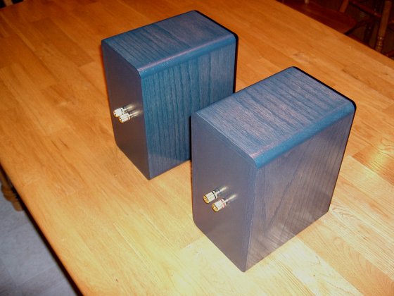
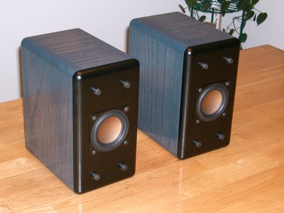
Rear / side view
Construction
I made the sides and top out of 1/2" solid oak. I just bought an 8" wide, 6 foot long quality piece of oak board and cut my parts out of it. The front, back and baffle fastening gussets were made out of MDF. The back and gussets were 3/4" while the removable front baffle can be 5/8" or 1/2".
The baffle is removable, and is fastened with socket head cap screws. Having the baffle removable allows easier placement of the filter inside the box. It also allows for usage of other speakers with construction of a new baffle. And finally, if you screw up the baffle, all is not lost - just make a new one and bolt it on.
The absolute most important thing to do when building the enclosure is to angle the back side of the driver cutout to promote airflow. Angle as in a chamfer, not a roundover. If you don't do that, Fs will go way up, and the sound will be compressed and colored. If you can't do it with a router, use a jigsaw with the blade at 45 degrees. Also note that the gussets are angled so they don't have a sharp reflection surface close to the driver. Other than that, there is some flexibility in how these are built. Give or take a half inch in any direction should be fine. I arrived at this particular enclosure shape to reach a few goals: the required volume, a smooth diffraction response and an attractive slim profile.
The desktop stands shown above are just an idea. I'm not supplying dimensions, construction techniques, a parts list or suppliers. It's just something to get you started. Also note that with this project I'm not recommending a 16 inch "mini desktop tower" version like I did with a previous project. The long internal dimension made it difficult to control internal reflections.
A 1/2" roundover on the front baffle is required. 3/4" is better if you have the tools to do it. A roundover on the side corners is optional, but I did it on mine because it looks better when solid oak is used.
What about the B3N round flange version?
When this project was in the preliminary stage, many people were wondering if the B3N was the same as the B3S. The driver is exactly the same except for the frame. Unfortunately, the frame causes some response differences in the top two octaves. The round flange version has more output in the 5khz region and less output in the 10khz region. Flush mounting the B3N makes a minor difference in the 2khz region, and in general it does not have to be done with this driver.
So the initial answer is that the B3N is slightly different. It can be used in place of the B3S, but the results will also slightly different. This design was optimized for the B3S version although the B3N will still sound pretty good with the same filter. The B3N does have some benefits - the frame is more rigid due to edge forming, and lets be honest, it looks better.
Full range power handling
Power Handling
With teeny weenie drivers like this, nothing is of bigger importance than power handling. The charts above are power doubling, starting at 1 watt, then 2 watts, then 4 watts, and on up to 128 watts. Careful, the 3mm Xmax shows up quickly. Running full range, don't expect to pump more than a few watts into it. You will exceed Xmax with 8 watts at 90hz. A Sonic Impact T-amp would make a nice combo for a nearfield or low level listening system. But for home theater or any other "room filling" sound, you had better start paying attention to the subwoofer crossover if you expect to get any reasonable loudness out of this system. Note: Thanks to John Kreskovsky for showing me how to set up filters in the Soundeasy enclosure design module so I can accurately look at Xmax issues when used with a sub.
"LR4" is 4th order Linkwitz-Riley and "LR2" is 2nd order of the same. Active filtering in HT receivers with bass management is usually LR4, and most receivers have some flexibility in the crossover point. for the best power handling, LR4 is preferable if you can use it. For most people, 150 hz is going to work best with these speakers. 100 hz will sound better due to lower localization of the sub, but will handle less power. 200hz will handle just about all the power you can give it, but sound worse due to sub localization and probably phase matching issues too. At 200 hz, sub placement becomes extremely important. Figure out your priorities and experiment with the crossover point. These speakers certainly seem to work well with my cheap Panasonic digital HT receiver set to 150hz. The Panny is a perfect LR4 active sub crossover with selections for 100, 150 and 200 hz.
The B3S is a low efficiency driver. That may concern some folks, but the more important thing is a driver's maximum output level. Watts are cheap these days, and I don't think you'll run out of them before the driver runs out of steam. There are more efficient 3" drivers out there, but ultimately most will run out of Xmax and start distorting sooner.
The minor details
Since it's a sealed enclosure, there is a broad range of damping that can be used. I used whispermat, but PE's Sonic Barrier would work fine, with the thickest stuff on the back and bottom, and 1/2" on the sides. Likewise, Acousti-stuf or regular dacron pillow stuffing would probably work fine also.
The socket head cap screws were 1/4-20 from Mcmaster-Carr and I used a few M6 washers under them. M6 metric washers fit 1/4" with a tighter tolerance. (less slop) The washers serve the purpose of allowing larger clearance holes which in turn allows some positioning of the baffle if your holes are a little off. (and they will be) Instead of normal T-nuts, I used PE's hurricane nuts which work much better.
Be *very* carefull tightening the screws that hold the the driver in place. Do not tighten them too tight or you will mutilate the small flat frame. Better yet, use some washers to help distribute the screw load.
I sealed the baffle with 3/8" x 1/8" low density weather stripping. You'll know it's the right stuff when you can compress it down to almost nothing. Using this stuff rather than the normal density tape helps keep the baffle from flexing outwardly when you tighten the cap screws. It still makes a good air seal though.
For those wondering about the dark blue finish seen in my pictures, It's Minwax Aegean blue. I let it dry well and then put a few coats of wipe-on Poly over it.
The B3S comes with a nice sealing gasket, but when you get it you should probably trim off 1/16" all the way around so it doesn't stick out from under the driver frame.
I used Madisound "POSTL" red and black for simple and cheap connection. Any terminal cup style would work fine also.
The filter components were epoxied to a board and placed on the side near the back. The two inductors were mounted on opposite ends of the board and at different angles to avoid electromagnetic interference.
There's not a whole lot of meat for the screw to grab into after angling the driver opening. You can add strenth to this area with a couple coats of wood glue to the soft exposed MDF area. The glue soaks in and hardens. Don't crank the screw too tight, you may strip the wood.
Summary
Inevitably, I will be asked: "Which sounds better, the Tangband W3-871 or the Hi-Vi B3S?" My answer is the B3S, which is why this page is replacing the old Tangband design. I've previously declared the TB 871 as the best 3" wide range driver, so the great sound of the HiVi B3S comes as a surprise. It's low price and wide availability are merely a bonus. A slightly more complicated filter and low efficiency is the only downside to this driver but that hardly matters when considering this driver's low distortion and wide bandwidth.
An entire great sounding home theater speaker system can be had for "garbage in a box" pricing. One driver plus it's filter parts will cost about $19. That brings it to under $100 for a 5 piece set of satellites. Add in whatever you need for enclosure parts and that's it. Round out the system with a good 8 or 10" sub and a cheap HT receiver, and get out the popcorn!
Enjoy!
Page done by John "Zaph" Krutke © 2005
Also visit -Zaph|Audio-