Zaph|Audio
Waveguide TMM
December 13, 2005 - Minor updates and corrections
September 16, 2005 - Added waveguide profile
Introduction
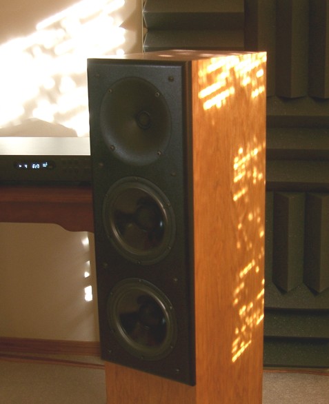
This project uses a Seas 27TDFC tweeter, a pair of Seas CA18RNX woofers and a modified MCM 54-580 6.5" horn lens. The same waveguide is also for sale at Teptronics if MCM happens to be out of stock. The drivers are configured in a 2.5-way "TMM" format, with a 2nd order Linkwitz-Riley crossover between the tweeter and the woofers. The enclosure is a tall floorstanding tower.
Some preliminary research shown on this web site leads up to this design.
The Seas CA18RNX is a good quality coated paper midwoofer. It's positives are high dynamic output, very smooth midrange response, deep bass response, low bass distortion, reasonable sensitivity and not too expensive. It's negatives are a merely average midrange harmonic distortion, an issue which is partially addressed by using two woofers. While the 2.5-way configuration only has the top woofer reproducing the upper midrange, the lower woofer relieves the upper woofer of increased bass levels required for baffle step compensation. The result is much cleaner output compared to a single woofer design.The Seas 27TDFC has been a long time favorite of DIY'ers. All drivers in the 27 C series have the same excellent motor and voice coil assembly, with the differences being the dome material and the surround. The TDF has a fabric sonotex dome with a rubber surround. While I slightly prefer the 27TBFCG in standard designs, it's hexagrid cover gets in the way of usage with a waveguide.
Oviously, the key to this design is the waveguide. The waveguide greatly reduces distortion at the low end of the tweeter's range. This particular waveguide layout works by raising the on-axis efficiency in a broad range between 1 and 6kHz. When the response curve is shaped back down to flat, harmonic distortion is reduced compared to a standard tweeter mounted on a flat baffle.
There are quite a few other benefits to waveguides. The low end of the tweeter's output has a change in directivity that more closely matches the woofer's directivity. The result is very smooth horizontal off axis response, and a power response that does not have the same deep null that a standard speaker would have. Related to the directivity benefit is the fact that a waveguide is not affected by the baffle it's on. Baffle diffraction is a non-issue compared to a standard dome mounted in an enclosure. In a waveguide system, you will not see the lower treble "ripple response" present in typical box systems. Fans of flat baffle dipoles, take note: with no cabinet depth, this is the worst case diffraction ripple. A waveguide is perfect for dipole usage, keeping the lower treble smooth.
The final benefit of a waveguide is that it moves the acoustic center of the tweeter back. In this case, by about 1.25 inches. This puts the listening axis straight forward in a standard LR2 design, and eliminates the need for a slanted baffle or the increased complexity of a ladder delay network. This combines with other benefits to greatly simplify crossover design. In fact, later on in this article you will be surprised just how simple the crossover can be in this design.
It's importantant to differentiate between a waveguide and a horn. A waveguide is generally shallow and has a wide throat with no compression chamber. This allows the system to maintain most of the benefits of standard dome design, with some of the low end directivity and response boost of horns. It truly is the best of both worlds, and my early "horn conversion" experiment shows that well.
I am presenting several different crossover designs - A minimalist version, a perfectionist version and "tube-friendly" versions of each of those. As such, I will first discuss the items common to all designs first, and then go over the crossover options last.
Enclosure
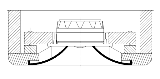
Waveguide Top View Cross Section
The listening axis, as determined by the crossover design shown later, is halfway between the top woofer and the tweeter. You may wish to adjust the height of the empty bottom chamber to match your normal listening position.
Waveguide construction is critical, and is detailed in these drawings. The first component is the backplate, which pushes the tweeter into the waveguide and holds it there with force. The second components are the mounting strips which glue to the back of the baffle. Generally, you will want to make these out of strong hardwood, since a lot of pressure is required to hold the tweeter in place. The final component is the tweeter baffle cutout, which must be countersunk. The tweeter lens should be held in place with socket head cap screws and T-nuts. The pressure from the back is pushing the waveguide out, and you need the strength of T-nuts to keep it in place. I used a thin sheet of foam between the tweeter and the waveguide to provide an air seal and prevent vibration.
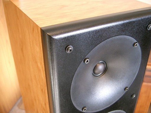
Waveguide Baffle Close-up
Modifying MCM 54-580
There are several ways to do this. I will document the one that I used. First I hacked off the metal horn threads with a hacksaw. Then I constructed a router jig. The jig consists of a base which has the horn screwed in face down, then a couple of spacer strips, and finally on top of that is a router "table" with a 4" hole in it to mill down the back so it's flat.
Milling depth is important, but the proper depth will be determined when the opening is the right size. The opening needs to be exactly 1.50 inches. When you mill down far enough that your opening is that size, you know your depth will be correct.
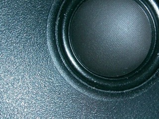
Waveguide Super Close-up
Milling down too far causes the waveguide to be too shallow, which will not give the proper response curve. Not milling down far enough will cause the edge of the waveguide to hang over the surround near the dome, which also has some response curve implications. When you get it just right, there will be a smooth transition from the roundover on the tweeter's flange to the start of the waveguide.
My advice is to buy a few of these in case you screw up. They're cheap anyway.
Drivers and Enclosure Tuning
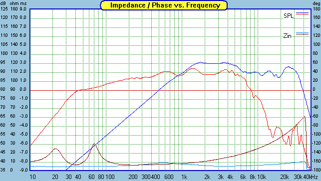
Raw In-box Response and Impedance Curves
The in-box response curves are quite different from the infinite baffle curves shown elsewhere. The tweeter, as discussed above, has a rise in response between 1 and 6kHz. It also has a mild peak above 20kHz, which is inaudible. I beleieve the small dip at 20kHz and peak at 25kHz is an artifact of the way the waveguide interfaces with the dome flange. That high up in the response curve makes it a non-issue.
The woofer, which is practically a flat line response curve on an infinite baffle, shows the baffle step reduction in bass when installed in the enclosure. There is also a minor dip/peak combo at 900 and 1500 hz, which I believe is related to cavity effect. This type of effect is normally limited to tweeters in an MTM, due to the woofer cone cavities above and below. In this case however, the cavities above and below the top woofer are from the waveguide and the lower .5 woofer. The effect is minor, but it does exist and may be slightly audible if it's not addressed in the crossover.
The power handling curve is for a single woofer tuned to 41hz in a 19.5 liter enclosure. It is power doubling starting with one watt. (1, 2, 4, 8... up to 128 watts) This does not change with the second woofer in parallel but you will get a 6dB boost in level. This is a *loud* speaker. Not just because of it's 90 dB sensitivity, but it handles a lot of power and is very dynamic. To date, this is the loudest speaker I have posted. I personally don't care for loud, but the bonus is that it remains very clean when it's cranked up no matter if it's classical or hard rock. With some lesser speakers, loud levels will hurt your ears.
I present a few bass tuning options - Mainly for those who like it low and lean (41hz), those who like a loud kickdrum impact (51hz), and one in between. (46hz) I encourage you to experiment with the tuning to find out what you like. I prefer the low and lean, and that curve is reflected in the responses shown here. Those Parts express ports (260-402) are cheap and can be cut in half and taped together so that there is a flare on the inside. They seem a bit small for this application, but having a flare on the inside greatly reduces turbulance. At $0.40 each, you can buy a whole bunch to experiment with. They press fit into a 2-9/16" hole.
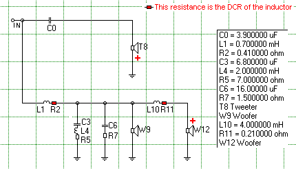
Crossover 1 - The Minimalist
I consider this crossover very special. In 20 years of building speakers, I've never come across a speaker design that works well with only one component on each driver. That changed with this system. The waveguide, if modified as per my instructions, allows for an excellent Linkwitz-Riley 2nd order slope with only a single capacitor on it. Likewise, each woofer only has one related component. The resulting response curve, while not perfect, is smooth enough for most people. Of course, crossover construction is super simple with only 3 components.
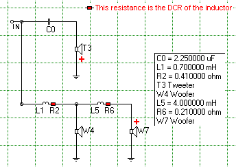
Minimalist crossover
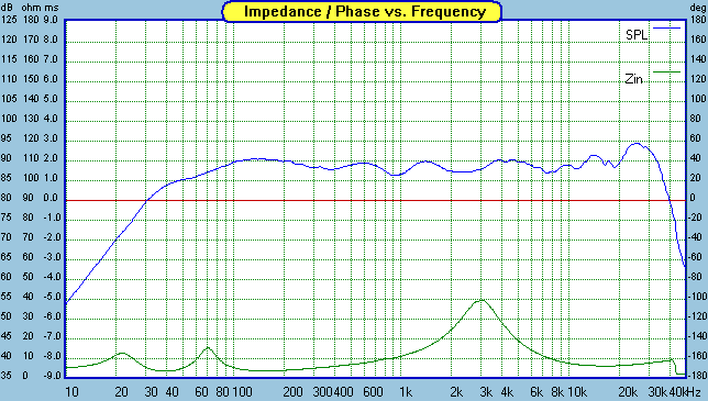
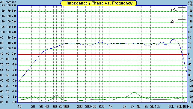
Minimalist Frequency Response and Impedance
The SPL of the drivers is just right so that no L-pad is needed on the tweeter. The response stays within a +/- 1.5 dB window for most of the range. As of this writing, I've listened to the system like this for over a month, and I'm still surprised how good it can sound with such a simple crossover.
This 2.5-way configuration was pioneered by Jeff Bagby a few years ago. The big baffle step inductor for the lower woofer comes after the crossover for the top woofer. The advantage is that the ultimate roll-off of the .5 woofer will now match that of the main woofer. Essentially, we get a 2.5 way with a cascaded slope that offers more control of the .5 driver top end response, without additional components. Another benefit is that the phase between the drivers will be in phase at low frequencies and only be 45 degrees apart at high frequencies, maintaining a good phase relationship between the woofers. It's so simple and elegant, I wish I'd thought of it, but hats off to Jeff.
A few concessions have been made in the interests of simplicity. The above images show those concessions. The reverse null... Well, it's kinda there. Phase tracking is acceptable but not exceptional. The driver responses are ok but not great. All this considered, vertical off axis response does not suffer much with a -10/+20 degree listening window. In the vertical off axis plot, blue is 1400hz, transitioning to red at 3200hz. A sharp null sets in at 23 degrees, so you better sit back down.The horizontal off-axis measurements show a strength of the waveguide's directivity. Even going waaay off axis does not cause a sudden sharp null in the response, but a gentle slope downwards. Vertical off-axis measurements match up well with the predicted. At +15 degrees a null shows up at 4kHz. Since this a sensitive speaker I thought I would offer an alternative crossover with an impedance compensation network. This should make it a little more friendly to tube amplifiers, provided they have 4 ohm taps. I'm not a fan of tube amps, but this circuit is easy enough to add. This speaker could make a flea power amp owner happy, provided the amp is 4 ohm stable.
Crossover 2 - The Perfectionist
Perfectionist crossover
Perfectionist Frequency Response and Impedance
The above crossover is very similar to the minimalist version but just does it better at the expense of more components. The tweeter still has a single cap on it, but the woofers have a few more components to control their responses. Note: The DCR of L4 needs to be included in the selection of the R5 resistor. In other words, if the DCR of L4 is one ohm, R5 should be 6 ohms.
As you can see with the above images, things are a bit more controlled with this crossover. Phase tracking is excellent and the drivers adhere closely to LR2 slopes for a good range on either side of the crossover point, before dropping off steeper. Vertical off axis response is taller and more symetrical. Once again, I offer a tube friendly version of the crossover without the impedance swing in the midrange.
Room setup suggestions
These speakers are relatively insensitive to room setup issues. It's not going to make much difference if you toe them in or not. While these speakers do have full baffle step compensation, they never sound boomy in small rooms. Place them so the rear of the cabinet is at least a foot out from the wall. Don't forget to play around with the tuning. The size of the room will make a big difference which tuning option works best, with smaller rooms generally working best with the low tuning, and large rooms with the higher tuning.
Options
With the minimalist crossover, if you want a little more lower treble and high midrange, or if you will be listening primarily off axis, change C0 to 2.7. Otherwise, a 2.2 will work fine. Do not change any values in the perfectionist version, this one is sensitive to changes. A bad cliche just popped into my head - Don't mess with perfection. Heheh.
While I generally don't recommend sealed enclosures with the CA18RNX woofers due to their low Qts, it certainly is possible in this design. Be prepared for about a 100hz F3 in the detailed enclosures, or about 90hz if you cut the enclosure depth by 4 or 5 inches. This will not integrate well with a sub unless you have assymmetrical LR4/LR2 crossovers, or run the mains full range and use an LR2 on the sub. (which doesn't help power handling or bass distortion at all)
Madisound's new tower cabinets could work pretty well for this project, but you should probably construct some risers or small stands maybe 6-10 inches high to get the listening axis up to ear height.
Those wishing to reproduce this project may be wondering which version of crossover to use. I'd recommend starting with the minimalist version. Then if you feel like upgrading later, the two inductors are still used in the perfectionist version. Note that the 4.0mH shown in both crossovers really is .21 ohms - It is a Madisound Sledgehammer Steel Laminate 15AWG, pretty much the only way you're going to get a DCR that low. The others are standard air cores.
Summary
This project is really a showcase for the waveguide. While I chose the Seas CA18RNX for the woofers, there are quite a few non-metal options that would work well with the waveguide, provided the crossover is updated. Of course, metal cone woofers would work fine too, but you won't get away with a 2nd order crossover in that case.
To duplicate this design, the waveguide has to be modified exactly as shown. If you want to break out on your own, there are several other ways to configure and/or modify the waveguide. In general, deeper waveguides will tend to boost the response more, provide a lot more directivity, and boost the power handling of the tweeter for a given sound level. Shallower waveguides will simply perform closer to a standard baffle mounted dome. Shallower waveguides seem to have a smoother top end response however. Pick your tradeoffs.
With this system, there seems to be a little less room interaction or early reflections in the mid treble. I noticed this after a few minutes with familiar music. It's a little hard to describe the effect, but it reminds me a bit of wearing a good pair of headphones except with forward imaging rather than "between the ears" imaging.
I have to say it was fun building a speaker with this level of dynamics and output. I value my ears and I don't do it too often, but I love cranking rock music on these as much as I love some good, dynamic classical or electric jazz.
Enjoy!
Page done by John "Zaph" Krutke © 2005
Also visit -Zaph|Audio-